Refrigerator and method of controlling the same

a technology of refrigerators and controls, which is applied in the field of refrigerators, can solve the problems of reducing the cooling efficiency and the inability to control the temperature of auxiliary storage independently, and achieve the effect of efficiently cooling an auxiliary storag

Inactive Publication Date: 2005-06-16
SAMSUNG ELECTRONICS CO LTD
View PDF13 Cites 26 Cited by
  • Summary
  • Abstract
  • Description
  • Claims
  • Application Information

AI Technical Summary

Benefits of technology

[0012] Accordingly, an aspect of the present invention provides a refrigera...

Problems solved by technology

However, in such case, there exists a problem that a temperature of the auxiliary storage cannot be controlled independently and the temperature of the auxiliary storage depends on a temperature of the...

Method used


Image

  • Refrigerator and method of controlling the same
  • Refrigerator and method of controlling the same
  • Refrigerator and method of controlling the same

Examples


first embodiment

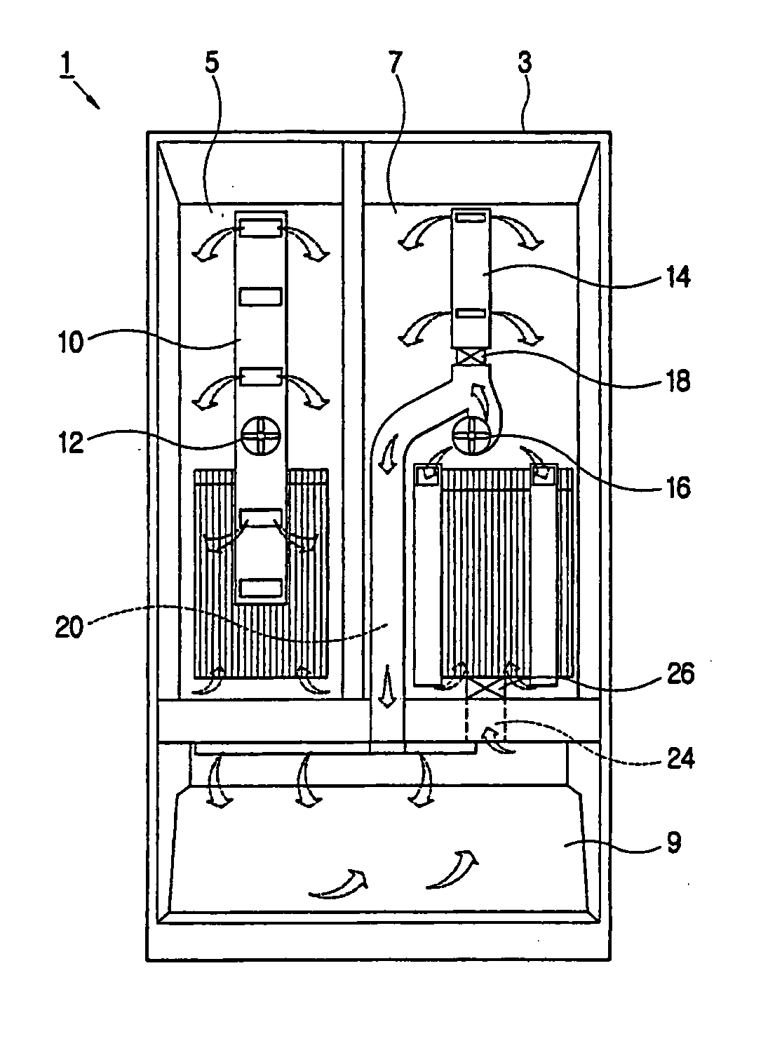
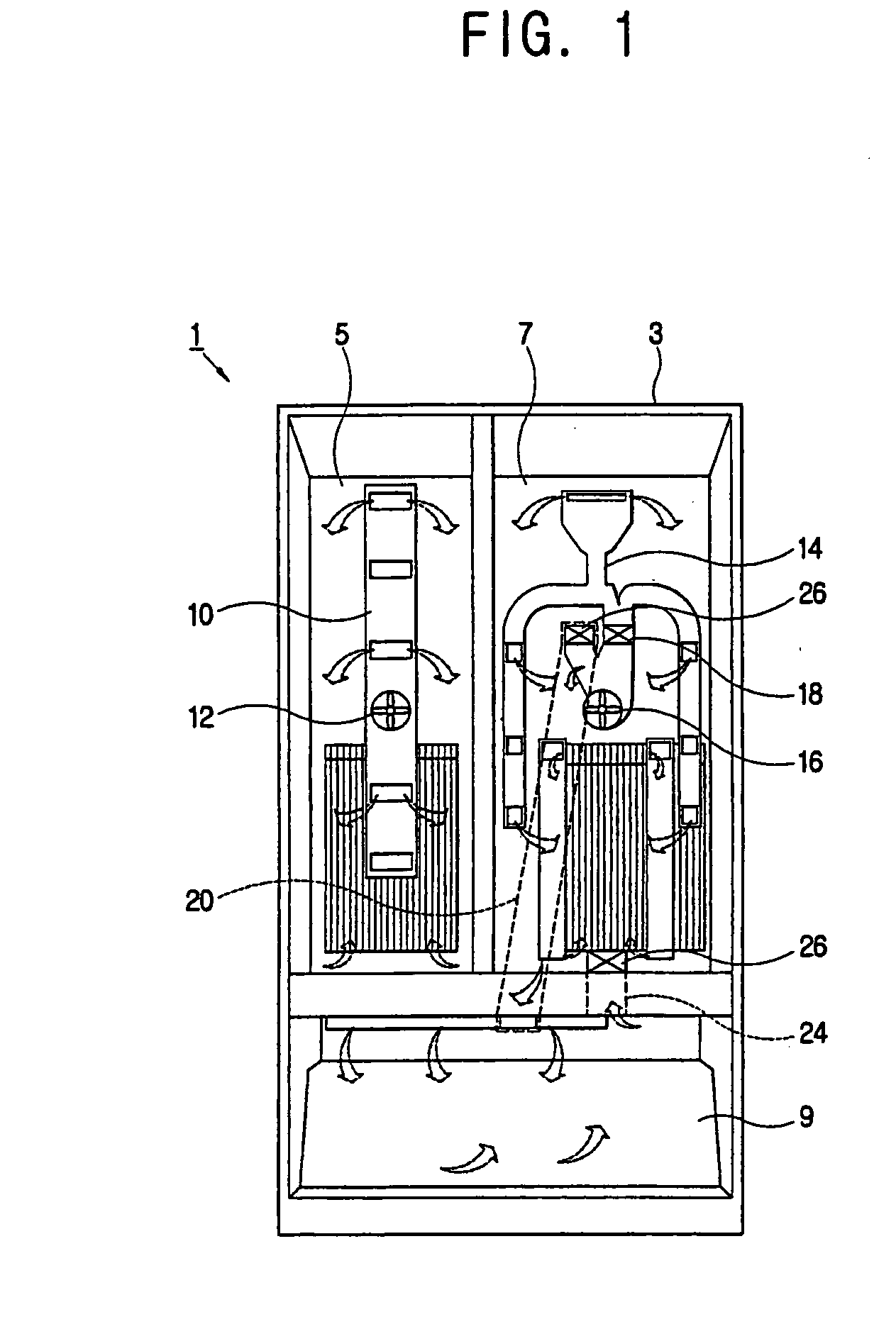
[0043]FIG. 1 is a schematic front view of a refrigerator according to the present invention. As shown therein, a refrigerator 1 according to the embodiment of the present invention comprises: a main body 3 forming a freezer compartment 5 on a left side and a refrigerator compartment 7 on a right side; a freezer compartment main duct 10 and a refrigerator compartment main duct 14 provided on rear surfaces of the freezer compartment 5 and the refrigerator compartment 7 of the main body 3, respectively, and comprising at least one exiting hole and one returning hole in each main duct; a freezer compartment evaporator (not shown) and a refrigerator compartment evaporator (not shown) installed in the freezer compartment main duct 10 and in the refrigerator compartment main duct 14, respectively, to generate cooling air; a freezer compartment fan 12 and a refrigerator compartment fan 16 to transfer the cooling air, generated from the freezer compartment evaporator and the refrigerator com...

third embodiment

[0050] In the refrigerator 1 the auxiliary supply duct 60, the auxiliary returning duct 64 and the auxiliary damper 66 are included in the freezer compartment 5 as an example.

[0051] Herein, the dampers 66 are included in the auxiliary supply duct 60 and the auxiliary returning duct 64. However, including the auxiliary damper 66 in one of the auxiliary supply duct 60 and the auxiliary returning duct 64 is also possible.

[0052]FIG. 4 is a control block diagram of the refrigerator 1 according to the first and second embodiments of the present invention.

[0053] As shown therein, the refrigerator 1 comprises: a refrigerator compartment temperature detector 32, a freezer compartment temperature detector 34, and an auxiliary storage temperature detector 36 to detect temperatures in the refrigerator compartment 7, the freezer compartment 5, and the auxiliary storage 9, respectively; a compressor driver 40 to drive a compressor 38; a refrigerator compartment fan driver 42 and a freezer comp...


PUM


Abstract

A refrigerator including [comprising a main body forming a refrigerator compartment and a freezer compartment, each of a freezer compartment main duct and a refrigerator compartment main duct comprising at least one exiting hole and one returning hole communicating respectively with the freezer compartment and the refrigerator compartment, a freezer compartment evaporator and a refrigerator compartment evaporator provided in the freezer compartment main duct and the refrigerator compartment main duct, respectively, and generating cooling air, and a freezer compartment fan and a refrigerator compartment fan provided in the freezer compartment main duct and the refrigerator compartment main duct, respectively, to let out the cooling air generated in the freezer compartment evaporator and the refrigerator compartment evaporator, respectively, through the exiting hole and to return the cooling air in the freezer compartment and the refrigerator compartment through the returning hole, comprising:] an auxiliary storage provided in a main body; an auxiliary supply duct, branched off from one of a freezer compartment main duct and a refrigerator compartment main duct, to supply the cooling air transferred by a corresponding fan to a auxiliary storage; an auxiliary returning duct returning the cooling air in the auxiliary storage to a corresponding main duct; and an auxiliary damper in at least one of the auxiliary supply duct and the auxiliary returning duct, to open and close to respectively supply and block the cooling air to the auxiliary storage.

Description

CROSS-REFERENCE TO RELATED APPLICATIONS [0001] This application claims the benefit of Korean Patent Application No. 2003-0090283, filed Dec. 11, 2003, in the Korean Intellectual Property Office, the disclosure of which is incorporated herein by reference. BACKGROUND OF THE INVENTION [0002] 1. Field of the Invention [0003] The present invention relates to a refrigerator and a method of controlling the same, and particularly to, a refrigerator and a method of controlling the same to efficiently cool an auxiliary storage. [0004] 2. Description of the Related Art [0005] A refrigerator generally comprises a main body formed with a refrigerator compartment and a freezer compartment, doors, installed in a front of the main body, to open and close front openings of the refrigerator and the freezer compartment, respectively, a compressor, a condenser, and an evaporator. [0006] Among conventional refrigerators, a refrigerator using an individual cooling method comprises: a main body forming a...

Claims


Application Information

Patent Timeline
IPC IPC(8): F25D17/08F25D11/02F25D17/04F25D17/06
CPCF25B2600/112F25D11/022F25D17/045F25D17/065F25D2317/061F25D2317/0682Y02B40/32F25D2400/06F25D2700/12F25D2700/121F25D2700/122F25D2700/123F25D2400/04Y02B40/00F25D17/08
Inventor LEE, JUNG-HOONLEE, JONG-DAL
Owner SAMSUNG ELECTRONICS CO LTD
Why Eureka
Try Eureka