

Multispindle lathe
- Summary
- Abstract
- Description
- Claims
- Application Information
AI Technical Summary
Benefits of technology
Problems solved by technology
Method used
Image

Examples
first embodiment
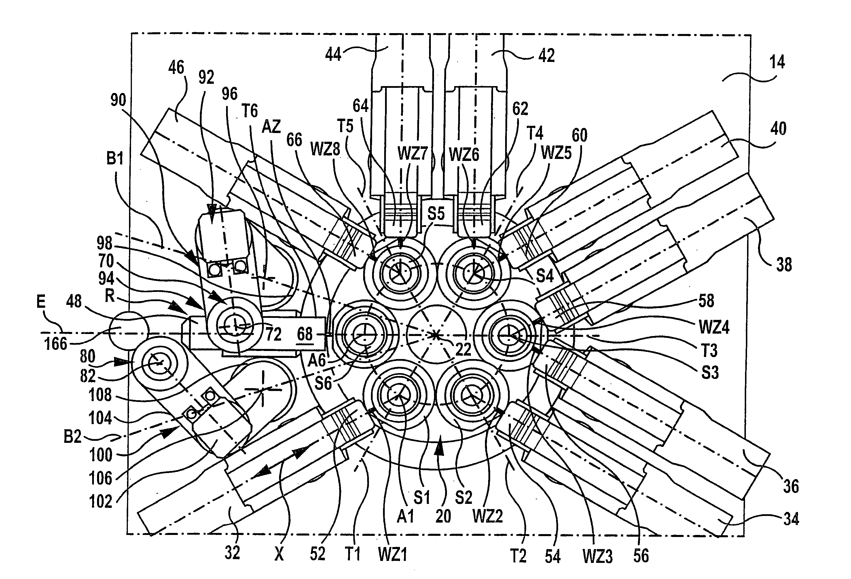
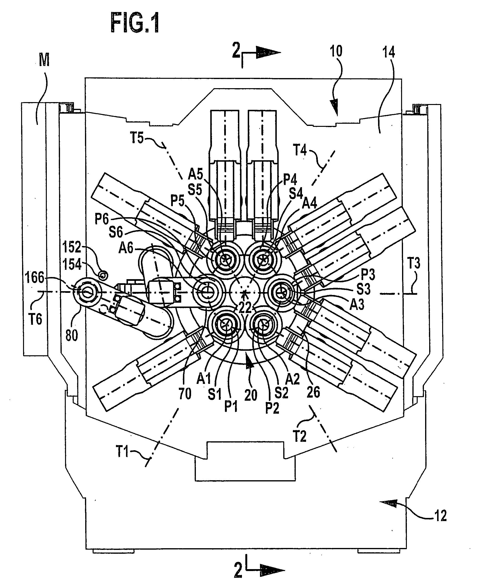
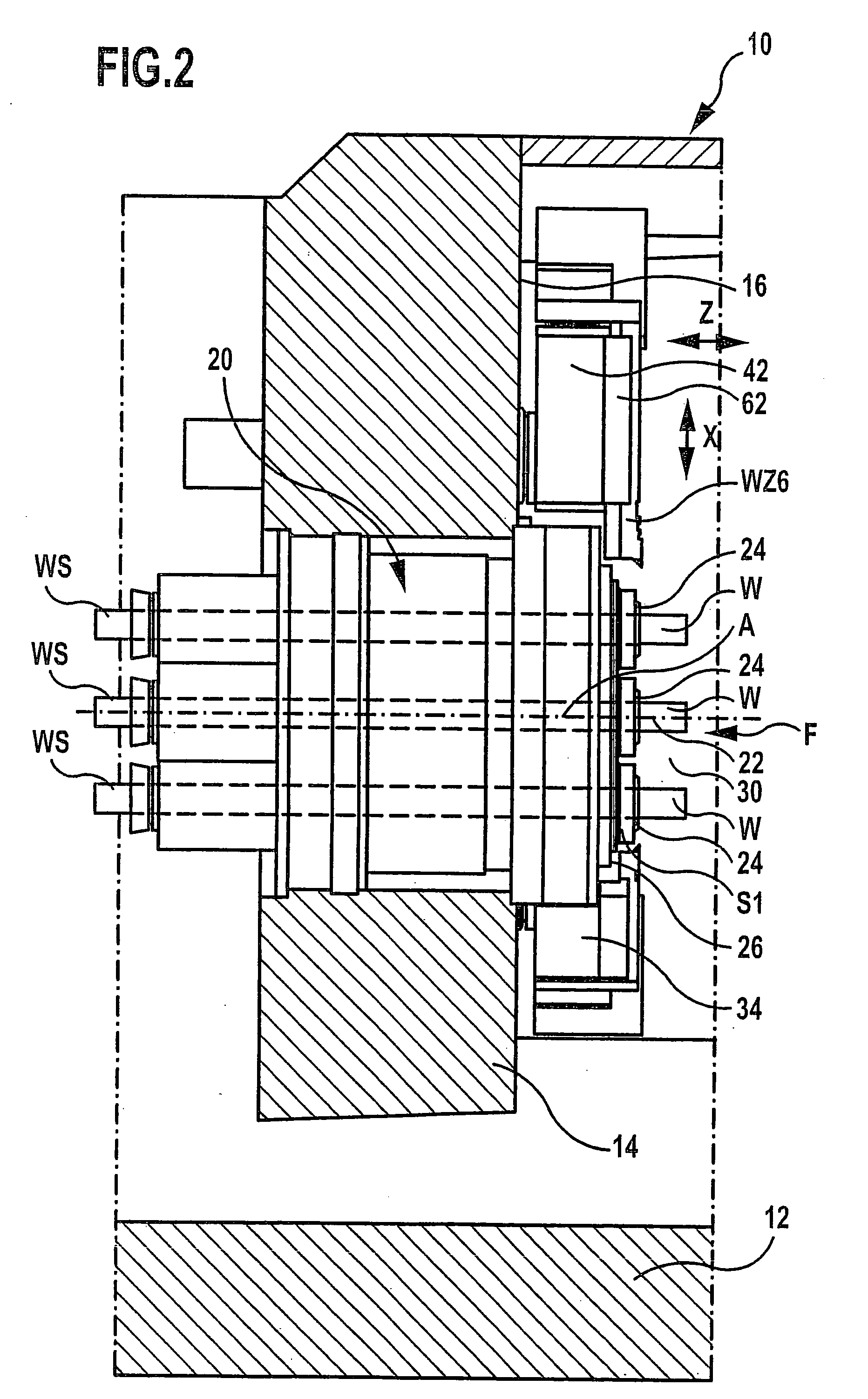
[0062] an inventive multispindle lathe, illustrated in FIGS. 1 and 2, comprises a machine frame denoted in its entirety by 10, with an underframe 12 and a stand 14 in which a spindle drum 20 is mounted for rotation about a spindle drum axis 22.
[0063] In the spindle drum 20, a plurality of workpiece spindles S1 to S6 are provided around the spindle drum axis 22 in spindle positions P1 to P6, which are preferably spaced at a distance from one another which corresponds to an angle of 360° divided by the number of workpiece spindles.
[0064] Each of the workpiece spindles S1 to S6 comprises a workpiece receiving means 24 for receiving a workpiece W. The workpiece W, as shown in FIG. 2, is formed in the first embodiment by a bar WS which is slidable through the corresponding workpiece spindle S and is preferably feedable by a magazine from a side located opposite the workpiece receiving means 24.
[0065] All workpiece spindles S1 to S6 are rotatingly drivable about their spindle axes A1 to...
second embodiment
[0102] In an inventive machine tool, shown in FIGS. 12 and 13, not only a workpiece removal device 166 is provided, but also a workpiece feeding device 168, so that the workpieces W are not fed in the form of bar WS through the individual workpiece spindles S, but can be made available via the workpiece feeding device 168 and received by the opposed spindles 70 or 80 in a workpiece receiving position therein, and, for example, a first machining of the workpieces W in the tools 154 and / or 164 can already be carried out before inserting the workpieces W in the workpiece spindles S of the spindle drum 20, so as to be able to already receive the workpieces W at a machined side thereof and, proceeding from this precisely machined side, then carry out the machining during passage through all spindle stations T.
[0103] The insertion of the thus pre-machined workpieces W is also carried out in a workpiece delivery position in spindle station T6, which, in this case, is designed both as workp...
PUM
| Property | Measurement | Unit |
|---|---|---|
| Angle | aaaaa | aaaaa |
| Area | aaaaa | aaaaa |
| Displacement | aaaaa | aaaaa |
Abstract
Description
Claims
Application Information