
Embossing system,components thereof, and methods

a technology of embossing system and embosser, which is applied in the field of embossing system, can solve the problems of large die cutters, expensive machines, and limited use of the embosser of the '693 patent for embossing a variety of different images, designs or patterns

Inactive Publication Date: 2005-06-16
QUICKUTZ
View PDF15 Cites 37 Cited by
  • Summary
  • Abstract
  • Description
  • Claims
  • Application Information

AI Technical Summary

Benefits of technology

[0021] A die that may be used in the system of the present invention comprises a thin, substantially planar member with a flat back side and one or more embossing elements protruding from a front side thereof. The embossing elements, which protrude a relatively short distance from the front side of the substantially planar member, form a design or pattern that may be reproduced by forming one or more indentations or impressions in a sheet of material. The die may also include one or more cutting edges that protrude from the front side of the substantially planar member and that are arranged in a design or pattern that may be reproduced in sheets of material by cutting into or through the sheets. The material from which the die is formed preferably facilitates repeated use of the die to cut the design or pattern into paper or another material. By way of example only, the die may be formed from a metal such as steel.
[0022] Optionally, the die may carry an element, referred to herein as a release element or an ejection element, that prevents an embossed and / or cut sheet of material from becoming trapped within the confines of the embossing or cutting edges. Such a release or ejection element may be formed from a compressible, resilient material (e.g., polyurethane foam or any other suitable material).

Problems solved by technology

The die and die counter of such presses are typically not removable therefrom, limiting the utility of such a press for use in forming a variety of different embossed images, designs, or patterns.
Further, the '389 and '464 Patents do not disclose that the embosser thereof may be used with any other apparatus to facilitate the formation of images in sheets of material or that the embosser could also be used to cut into or through the sheet of material.
Use of the embosser of the '693 Patent is limited to embossing a sheet of material.
Nonetheless, conventional die cutters are large, expensive machines and, as a result, their availability to individuals has been limited.
The practical use of such die cutting devices is limited to large-scale commercial production.
Thus, each such die is part of a somewhat complex die cutting device and, as a result, may be undesirably large.
The table-top presses of such die cutting kits or systems are also relatively large.
Consequently, the size of image that can be formed with the ribbon or strip of metal is size-limited to a degree that depends upon the thickness of the metal ribbon or strip, as well as on the capabilities of a die forming apparatus.
The shapes that may be formed with conventional paper punches are similarly noncomplex, making them somewhat undesirable for use in decorative applications, such as in scrapbooking and creating displays.
Moreover, the cuttings formed by paper punches are often undesirably small for use in applications, such as on posters, bulletin boards, or other displays, where visibility from a distance is desired.
As a consequence of the unavailability of conventional die cutting apparatus and the noncomplexity and small sizes of cutting formed by paper punches, individuals who wanted to use letters of the alphabet or other images formed from paper, card stock, or sheets of other materials often had to cut these images by hand.
Nonetheless, currently available hand-operated and thumb-operated punches from which cut paper may be readily removed are typically not capable of forming images with internal holes, such as the internal holes of many letters of the alphabet (e.g., a, b, d, e, g, o, etc.).
As with the previously discussed die cutting system, a relatively large amount of space would be required to store an alphabet sized set of these hand-operated punches.
As one of the outer and inner sets of cooperating punch elements is recessed relative to the other to facilitate the formation of a pattern with internal holes, however, the cut pattern typically becomes trapped within such a punch.

Method used


Image

  • Embossing system,components thereof, and methods
  • Embossing system,components thereof, and methods
  • Embossing system,components thereof, and methods

Examples


Embodiment Construction

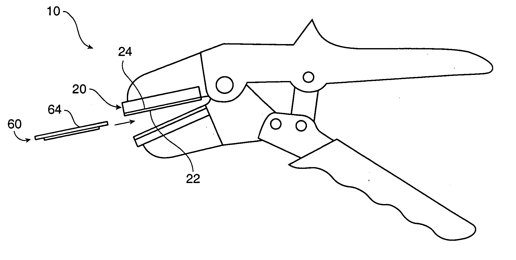
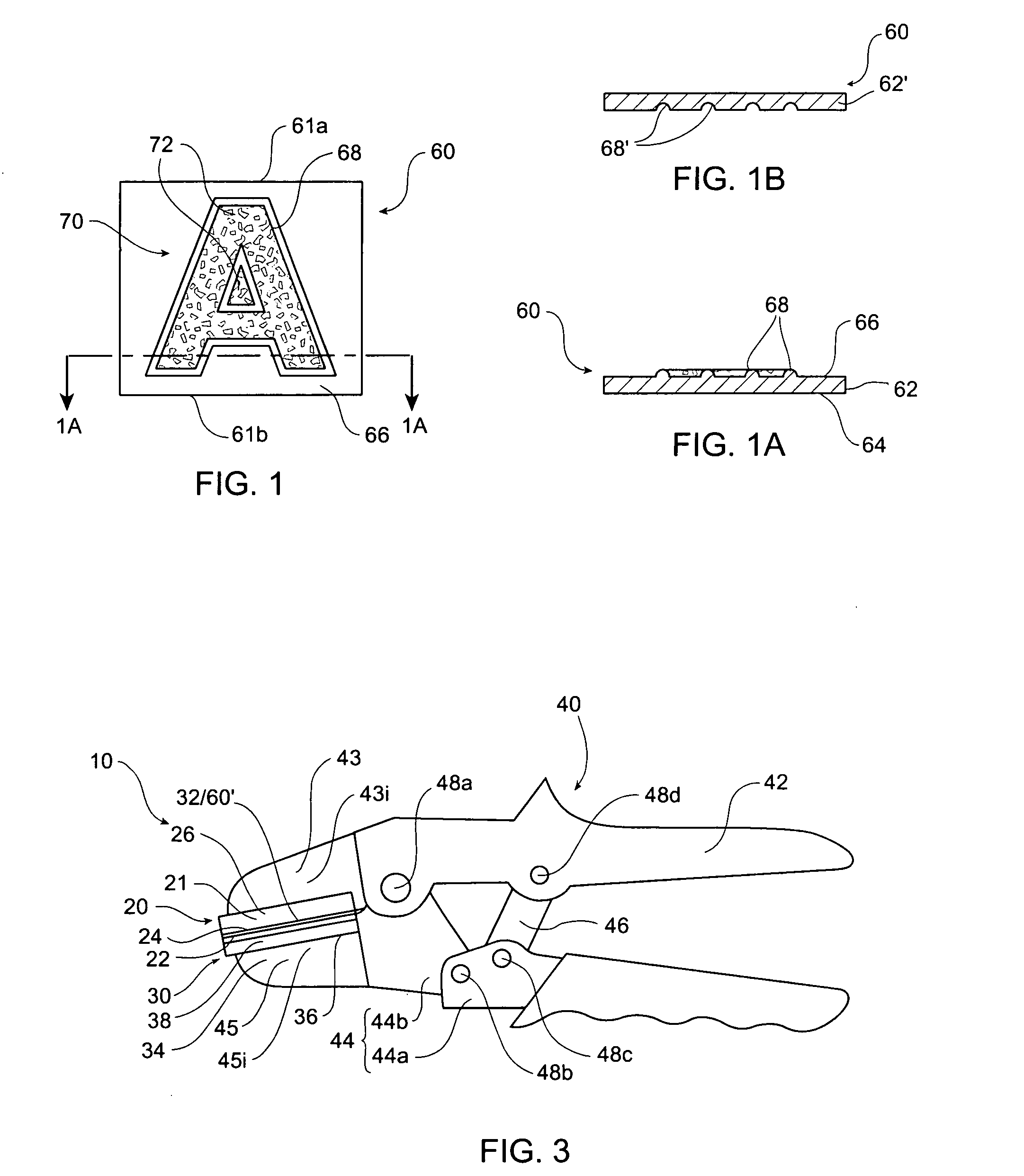
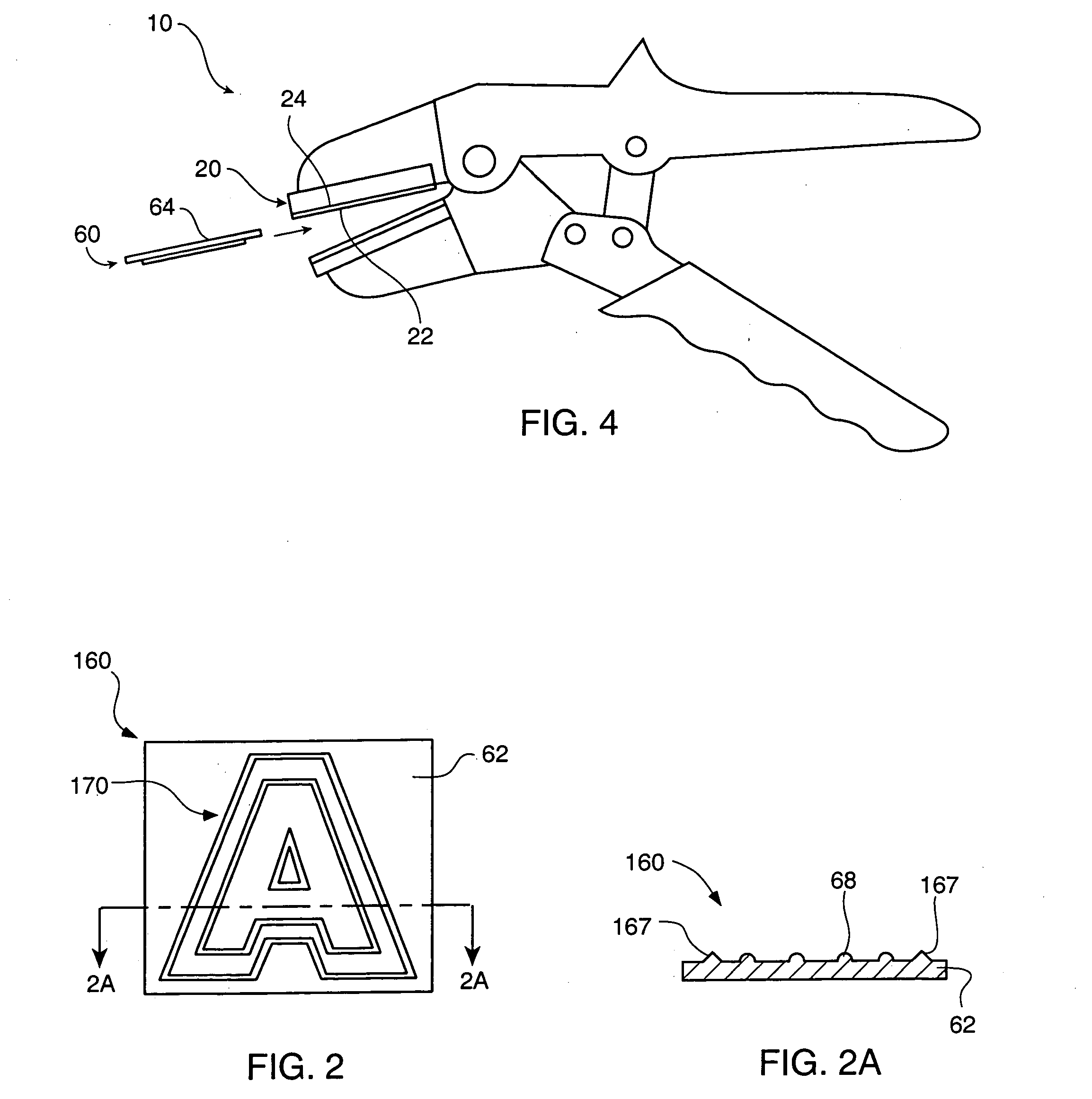
[0040] With reference to FIGS. 1 and 1A, an embossing die 60 is illustrated. Embossing die 60 includes a thin, plate 62 with a back side 64 and embossing elements 68 protruding a short distance from a front side 66 of plate 62. Plate 62 may comprise a substantially planar member, with back side 64 being a substantially planar surface thereof. Plate 62 and embossing elements 68 thereof may comprise a substantially unitary structure. Embossing elements 68 forms a design or pattern 70 to be impressed, or embossed, into a sheet of material.

[0041] The lateral dimensions of each embossing element 68, as well as the material from which each embossing element 68 is formed, preferably impart embossing elements 68 with the ability to withstand repeated use while minimizing the amount of pressure required for forming an indentation in a sheet of material. The shape of each embossing element 68 may be configured to prevent embossing element 68 from cutting through the sheet of material. As an ...


PUM


Abstract

An embossing die includes a plate and at least one embossing element protruding from a surface thereof. The embossing die may also include at least one cutting edge protruding from the surface of the plate. An embossing system that includes the embossing die may also include a press. The press may be manually operated and may be hand-held or supported upon a flat surface, such as a tabletop. A first member of the press receives the embossing die, while a second member of the press provides support for a sheet of material into or from which the embossing die will form a pattern upon biasing the die against the sheet of material. Manually operated presses and die embossing methods that employ teachings of the invention are also disclosed.

Description

CROSS-REFERENCE TO RELATED APPLICATIONS [0001] This application is a continuation of PCT Patent Application Serial No. PCT / US / 02 / 26117, filed Aug. 15, 2002, now International Publication No. WO 03 / 016035 A1, published Feb. 27, 2003, which application claims priority to U.S. Provisional Patent Application Ser. No. 60 / 312,512, filed Aug. 15, 2001, abandoned.BACKGROUND OF THE INVENTION [0002] 1. Field of the Invention [0003] The present invention relates generally to embossing equipment for use with sheets of paper, card stock, plastic, fabric, metal (i.e., foil), and the like. More specifically, the present invention relates to embossing systems which include compact dies. The present invention also relates to hand-held die embossers. In addition, the present invention relates to die cutting equipment for use with sheets of material. [0004] 2. Background of the Related Art [0005] The use of embossers to form decorative images or to impress seals into sheets of material, such as paper ...

Claims


Application Information

Patent Timeline
Patent Type & Authority Applications(United States)
IPC IPC(8): B31F1/07B44B5/00
CPCB31F1/07B44B5/0085B44B5/0038B31F2201/0705
Inventor HIXON, NATASHA P.HIXON, MARK A.
Owner QUICKUTZ
Learn More