Binocular stereoscopic observation apparatus, electronic image stereomicroscope, electronic image stereoscopic observation apparatus, and electronic image observation apparatus

a stereoscopic observation and electronic image technology, applied in the direction of instruments, color television details, telescopes, etc., can solve the problems of small depth of optical system of imaging section, poor reproducibility in direction,

Inactive Publication Date: 2005-06-16
OLYMPUS CORP
View PDF2 Cites 16 Cited by
  • Summary
  • Abstract
  • Description
  • Claims
  • Application Information

AI Technical Summary

Problems solved by technology

In such a stereoscopic imaging apparatus, when the depth of the optical system of the imaging section is enlarged, resolution is impaired, while when an aperture is increased to improve the resolution, the depth of the optical system of the imaging section becomes small.
In such a stereo image, it is known that a simple portion corresponding to the two images with parallax (for examp...

Method used


Image

  • Binocular stereoscopic observation apparatus, electronic image stereomicroscope, electronic image stereoscopic observation apparatus, and electronic image observation apparatus
  • Binocular stereoscopic observation apparatus, electronic image stereomicroscope, electronic image stereoscopic observation apparatus, and electronic image observation apparatus
  • Binocular stereoscopic observation apparatus, electronic image stereomicroscope, electronic image stereoscopic observation apparatus, and electronic image observation apparatus

Examples


first embodiment

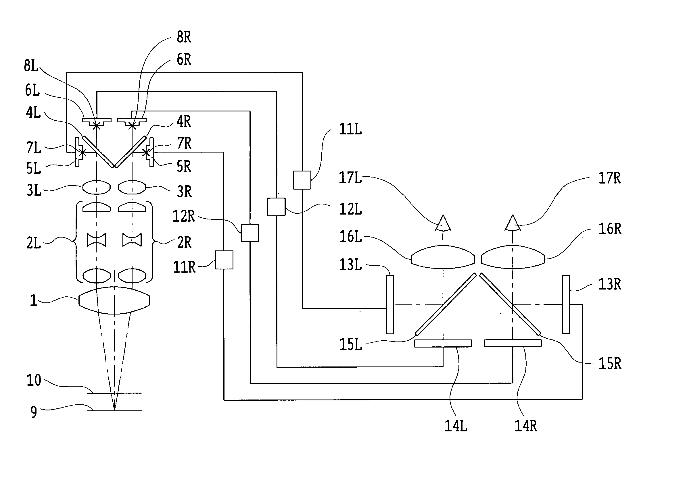
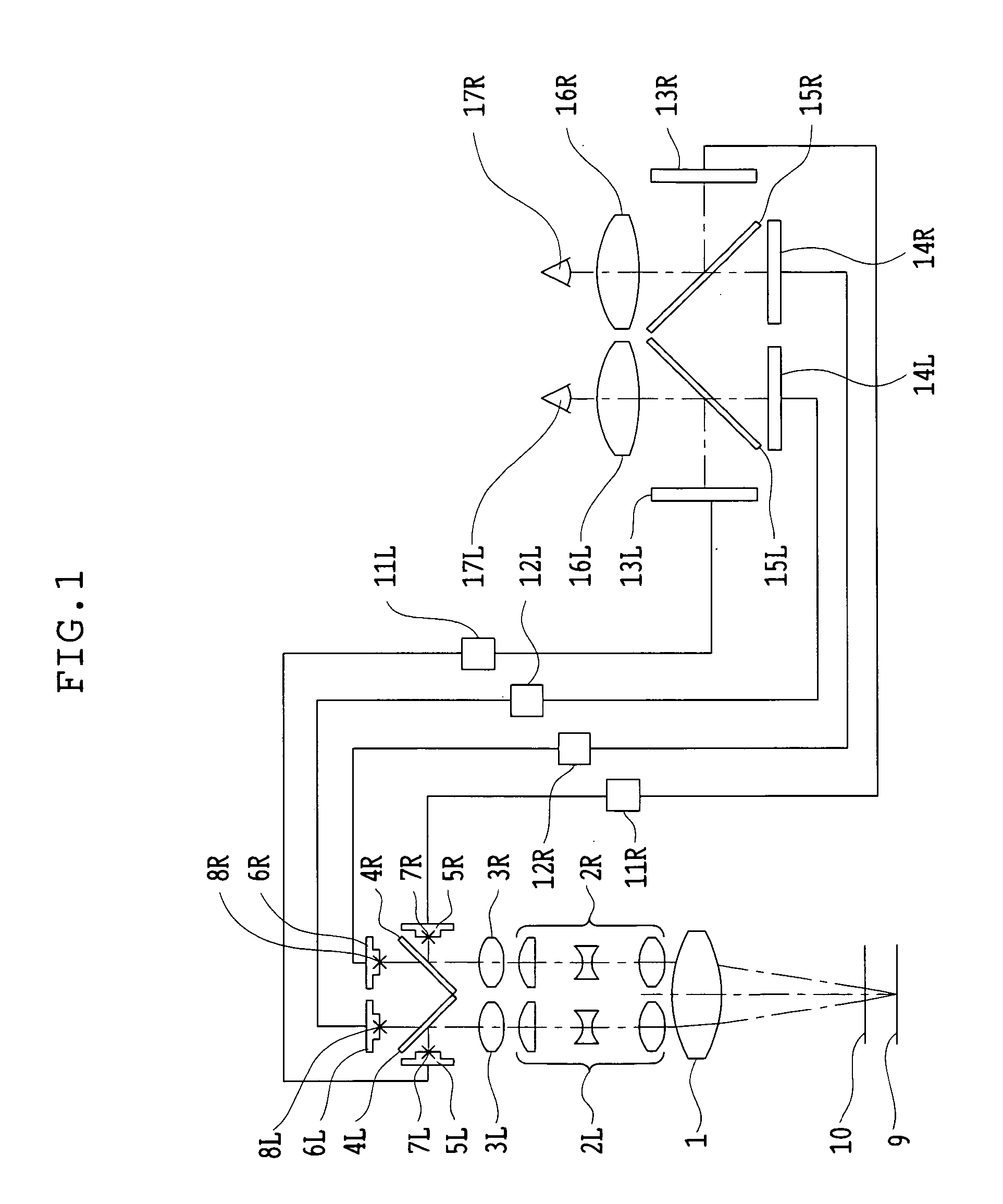
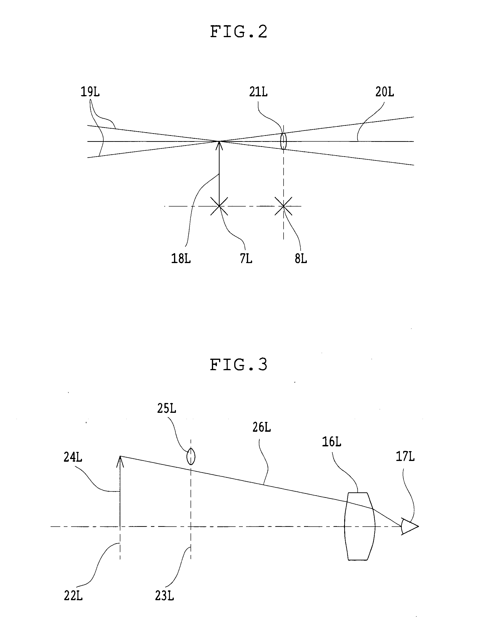
[0048]FIG. 1 shows the binocular stereoscopic observation apparatus of the first embodiment in the present invention.

[0049] The binocular stereoscopic observation apparatus of the first embodiment includes an imaging section forming images of an object to be observed and an observing section in which formed images are observed by a viewer. The imaging section is constructed to have a pair of left and right optical systems forming images with parallax and to form two images at different focus positions in each of the left and right optical systems. The observing section is constructed so that the images formed at the different focus positions in each optical system of the imaging section are displayed at a plurality of display positions and these images are observed with the eyes and thereby are superimposed.

[0050] The imaging section has an objective lens 1 and a pair of left and right imaging optical systems that includes a pair of left and right afocal zoom lenses 2L and 2R and ...

second embodiment

[0061]FIG. 6 shows the binocular stereoscopic observation apparatus of the second embodiment in the present invention.

[0062] The binocular stereoscopic observation apparatus of the second embodiment includes an imaging section forming images of an object to be observed and an observing section in which formed images are observed by a viewer. The imaging section of the second embodiment has n image sensors on each of the left and right optical paths.

[0063] Specifically, the imaging section has a variable-WD objective unit 32; a pair of left and right imaging optical systems that includes a pair of left and right afocal zoom lenses 33L and 33R and a pair of left and right imaging lenses 34L and 34R; light-splitting elements 35L1-35Ln-1 and 35R1-35Rn-1; mirrors 36L and 36R; and image sensors 37L1-37Ln and 37R1-37Rn. In this figure, symbol L attached to each reference numeral indicates the left-eye optical path and R indicates the right-eye optical path. The subscript of each referenc...


PUM


Abstract

A binocular stereoscopic observation apparatus includes an imaging section forming left and right images with parallax in at least two directions and an observing section in which the images with parallax are stereoscopically observed with a viewer's eyes. In this case, the imaging section has an imaging lens forming images of an object at imaging positions on each of left and right optical paths and i imaging positions on the optical axis of the imaging lens, satisfying the following conditions:
L(j−1)<Lj
Ek=Lj−L(j−1)
Dd<Ek
where Lj is a distance, measured along the optical axis, from the imaging lens to the jth imaging position, Ek is a difference between distances, measured along the optical axis, from adjacent imaging positions to the imaging lens, and Dd is an image-side depth of an optical system of the imaging section. The observing section has an eyepiece optical system and i display devices on each of the left and right optical paths so that an image formed at the jth imaging position from the imaging lens on each optical path of the imaging section is displayed on the jth display device from the eyepiece optical system on a corresponding optical path, satisfying the following condition:
Mj<M(j−1)
where Mj is a distance, measured along the optical axis, from the eyepiece optical system to the jth display device. The observing section further has means for superimposing i displayed images on a viewer's pupil. Here, i is an integer of 2 or more and j is an integer satisfying conditions, 1≦j≦i and j≧2.

Description

[0001] The contents of Application No. 2003-281998 filed on Jul. 29, 2003, in Japan, are hereby incorporated by reference. BACKGROUND OF THE INVENTION [0002] 1. Field of the Invention [0003] This invention relates to a binocular stereoscopic observation apparatus, an electronic image stereomicroscope, an electronic image stereoscopic observation apparatus, and an electronic image observation apparatus that are suitable for the application of work to an object to be observed. [0004] 2. Description of Related Art [0005] In conventional practice, a stereomicroscope has been used to perform a surgical operation under a microscope that requires processing work of minute portions and accurate work in a narrow region on the periphery of an affected part. Recently, it has been desired that such work should be carried out by remote control. This is because if the work can be carried out by remote control, the work and the surgical operation can be performed at various places without moving w...

Claims


Application Information

Patent Timeline
IPC IPC(8): G02B21/22G02B27/22H04N13/00
CPCH04N13/044H04N13/0239H04N13/239H04N13/344
Inventor HANZAWA, TOYOHARU
Owner OLYMPUS CORP
Why Eureka
Try Eureka