
Image photographing device and method

a technology of image and photographing device, which is applied in the direction of radio frequency controlled devices, printers, instruments, etc., can solve the problems of inability to use motor-using af functions, inability to control focus length, and inability to accurately calculate distances

Inactive Publication Date: 2005-06-16
SAMSUNG ELECTRONICS CO LTD
View PDF2 Cites 85 Cited by
  • Summary
  • Abstract
  • Description
  • Claims
  • Application Information

AI Technical Summary

Benefits of technology

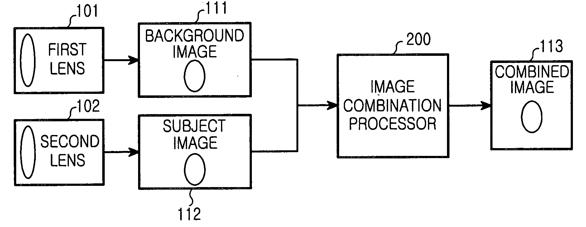
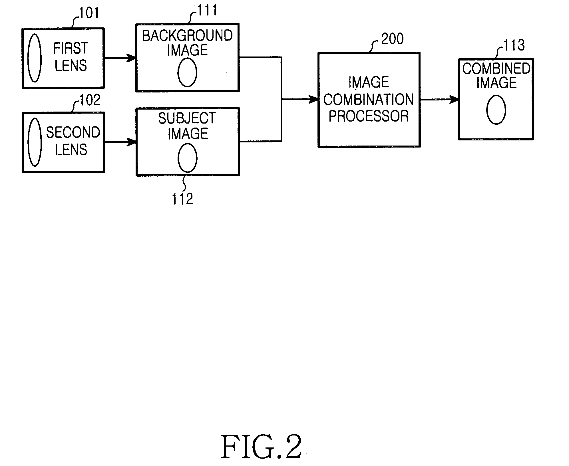
The present invention provides an image photographing device and method that can capture distortion-free, precise images with front to back scenes brought into focus. It can also join images with different focal lengths by an image processing technique in a camera phone, prevent image distortions and achieve a precise focus using a standard lens instead of a wide-angle lens in a camera phone, and stitch a subject to a different background by replacing an existing background with the new one in an image. The device and method capture images at different focal lengths simultaneously, segment each image into a predetermined number of blocks, select an in-focus block between every pair of blocks, and generate a final combined image using the in-focus blocks. The method can also capture images at different focal lengths at different time points and combine them into a final combined image.

Problems solved by technology

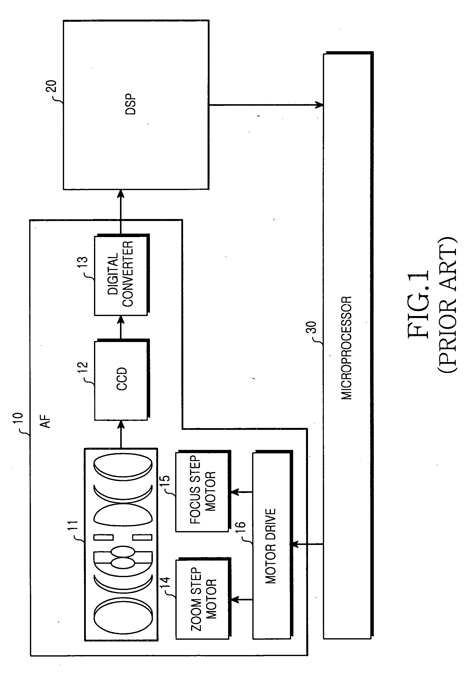
However, this method has the shortcomings that there is a limit on control of the focus length, the distance calculation is not accurate, and an additional device is needed for the distance calculation.
Meanwhile, the motor-using AF function is not viable for small-size cameras because a motor occupies a large space.
However, the use of the wide-angle lens causes distortions in the image and makes the background look farther away than it really is.
Also, the distortions are more serious in nearby objects.
Hence, it is difficult to focus on an object within a range of 1 meter.
Since a narrow iris reduces exposure, the shutter speed must be decreased, thereby impairing the clearness of the image.
Yet, it has some limitations in improving image quality because though the resolution of an image sensor increases, the AF function is omitted.
However, adding the AF function is difficult because it requires a large area in a small-size device like a camera phone.

Method used


Image

  • Image photographing device and method
  • Image photographing device and method
  • Image photographing device and method

Examples


second embodiment

[0069]FIG. 12 is a detailed block diagram of the image combination processor according to the present invention.

[0070] Referring to FIG. 12, the image combination processor 300 includes the block matrix unit 210 for detecting high frequency components and generating an initial block matrix, the filter unit 220 for filtering a predetermined block value in the initial block matrix, a compensator 310 for correcting errors by extending filtered blocks, and the image combiner 230 for stitching compensated high frequency blocks, that is, the subject image 112 to the background image 111.

[0071] The block matrix unit 210 includes the block segmenter 211 for segmenting the background image 111 and the subject image 112 into blocks, the DCT 212 for representing the blocks in the frequency domain, the high frequency detector 213 for detecting high frequency components from the frequency-domain blocks, and the initial block matrix generator 214 for generating an initial block matrix out of the...

first embodiment

[0077] The background and subject images 111 and 112 are segmented into blocks and DCT-converted in the block matrix unit 210. The DCT is performed in the same manner as in the present invention and thus its detailed description is not provided here.

[0078] DCT blocks 402 are converted to high frequency blocks 403 in the high frequency detector 213. The frequency components of each of them are summed vertically and horizontally and a high frequency block having the most high frequency components is selected as an in-focus block. The DCT 212 can be implemented by using an existing DCT device mounted for video compression without being separately procured. The block values of the high frequency blocks 403 are determined in the initial block matrix decider 214 in the manner described with reference to FIG. 5.

[0079] After selecting the high frequency blocks, the initial block matrix is generated by calculating the block values f(i, j) of the blocks. f(i, j) is set to 0 if the subject im...


PUM


Abstract

An image photographing device and method for combining images with different focal lengths to an in-focus image are provided. In the image photographing device, at least one lens captures images for focusing on scenes having different distances, and an image combination processor segments each of the images into a predetermined number of blocks, selects an in-focus block between every pair of blocks at the same position in the images, and generates a final combined image using the in-focus blocks.

Description

PRIORITY [0001] This application claims the benefit under 35 U.S.C. §119(a) of an application entitled “Image Photographing Device and Method” filed in the Korean Intellectual Property Office on Oct. 31, 2003 and assigned Serial No. 2003-76877, the entire contents of which are incorporated herein by reference. BACKGROUND OF THE INVENTION [0002] 1. Field of the Invention [0003] The present invention relates generally to an image photographing device and method. In particular, the present invention relates to an image photographing device and method for combining images with different focal lengths to an in-focus image in a digital camera used for a portable terminal. [0004] 2. Description of the Related Art [0005] A digital camera and a camcorder use an Auto Focus (AF) device to focus on a subject. The AF typically controls the position of a lens by using a motor. [0006]FIG. 1 is a block diagram of an image photographing device in a camera including a conventional AF device. [0007] R...

Claims


Application Information

Patent Timeline
Patent Type & Authority Applications(United States)
IPC IPC(8): H01L27/148H04B1/40H04N5/262
CPCG03B29/00H01L27/148H04N5/265H04N5/23212H04N5/23232H04N5/2258H04N23/45H04N23/673H04N23/951H04B1/40
Inventor CHOI, KWANG-CHEOL
Owner SAMSUNG ELECTRONICS CO LTD
Learn More