Light tube system for distributing sunlight or artificial light singly or in combination

a technology of artificial light and light tube, which is applied in the field of light tube system for distributing sunlight or artificial light singly or in combination, and can solve the problems of inability to meet the needs of lighting,

Inactive Publication Date: 2005-06-16
EISENMAN JAMES A +1
View PDF0 Cites 28 Cited by
  • Summary
  • Abstract
  • Description
  • Claims
  • Application Information

AI Technical Summary

Benefits of technology

[0011] Another preferred embodiment described in further detail below comprises two sets of larger-smaller parabolic reflectors arranged to minimize the losses inherently caused by the position of the smaller parabolic reflector in the path of the sun striking the larger parabolic reflector.
[0013] According to another aspect of the present invention, one or more of the several reflectors in the system can be made to separate the visible spectrum of the light from the invisible (including infra red). The visible light can be directed into the light distribution system while the invisible light can be filtered to eliminate it. The visible light will be “cool”, significantly lowering the demand for air conditioning. Another advantage of the present systems is that they allow the artificial light sources to be centralized where their excess heat can be vented to the outdoors in warm weather and into the building in cold weather.

Problems solved by technology

Fossil fuel is a finite resource, the burning of which has incipient environmental consequences.
Photovoltaic generation of electricity is a broad, high tech energy source but still has limitations with respect to scale and storage.
Except for window panes and sky lights, however, interior solar lighting has been clumsy, costly and difficult because both the intensity and the angles of sunlight vary so widely with time of day, with the seasons, and with the weather.

Method used


Image

  • Light tube system for distributing sunlight or artificial light singly or in combination
  • Light tube system for distributing sunlight or artificial light singly or in combination
  • Light tube system for distributing sunlight or artificial light singly or in combination

Examples


Embodiment Construction

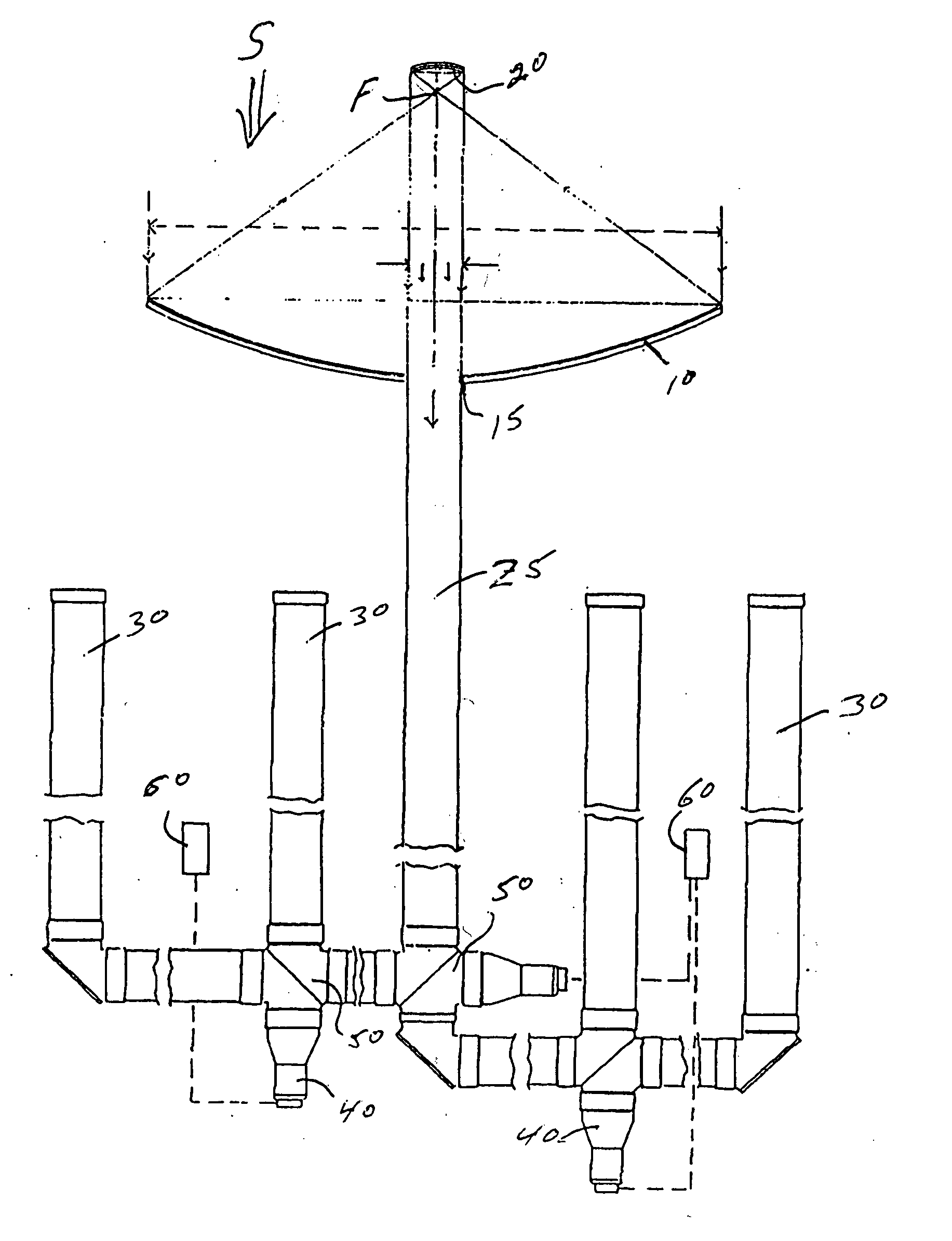
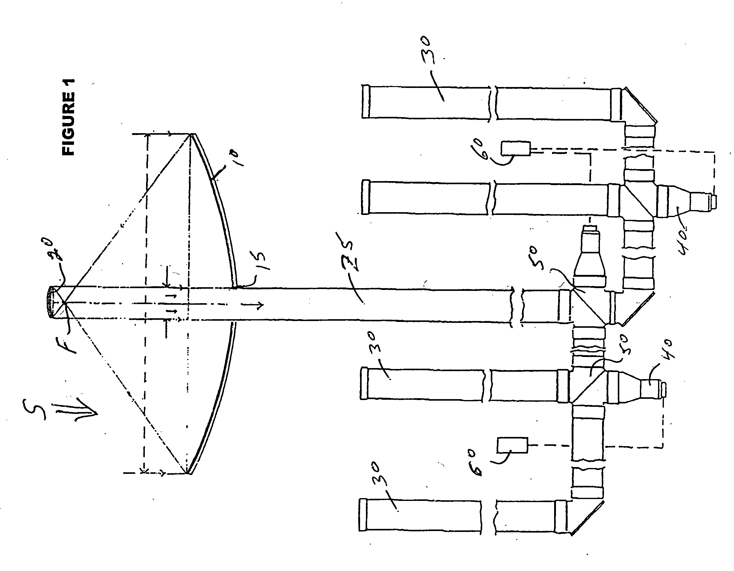
[0039] Various embodiments of the present invention relate to systems for collecting and concentrating sunlight and directing concentrated sunlight and / or collimated artificial light into at least one light distributor tube. FIG. 1 is a schematic of one embodiment of the present invention comprising a parabolic reflector 10 having a central through hole 15 which allows for the passage for concentrated sunlight reflected off parabolic reflector 20. Parabolic reflector 10 and concave parabolic reflector 20 are positioned to share a common focal point F such that sunlight entering in the direction of arrow S will strike parabolic reflector 10 and be reflected to concave parabolic reflector 20 which will then reflect the light through the central hole 15 in parabolic reflector 10. The combination of the parabolic reflector 10 and concave parabolic reflector 20 concentrate and recollimate the sunlight for introduction into a single distributor system. This illustrated system also compris...


PUM


Abstract

Hybrid lighting systems use light distributor tubes to distribute artificial light and natural sunlight through the same distributor tubes. Devices for gathering uncollimated light from conventional sources (such as electrically energized arcs or filaments housed in evacuated or gas filled glass envelopes) and directing the light into the ends of tubes designed to distribute such light. Devices for gathering and concentrating inherently collimated sunlight to be fed into the same light distributing tubes used by the artificial light. One preferred embodiment comprises a light gathering and concentrating system in the form of a pair of opposed parabolic reflectors, one which is preferably large, e.g. having a diameter of five feet, and the other much smaller, e.g. the size of the much smaller distribution tubes. This light gathering system is connected to the light distribution tubes through a pair 90° elbows which are rotatable in the X and Y axis in order to track the location of the sun in the sky. The two parabolic reflectors are positioned to share a common focal point so that the larger reflector will direct the sunlight through the focal point of the smaller reflector, which will, reflect the light as concentrated, collimated light. A central aperture in the larger reflector passes the concentrated beam on its way to the distribution tubes.

Description

RELATED APPLICATION DATA [0001] This application claims the benefits of U.S. Provisional Patent Application No. 60\221,604 filed on Jul. 28, 2000.[0002] The present invention is related to lighting systems using sunlight, artificial light or both simultaneously in any proportion in a common light distribution system. BACKGROUND OF THE INVENTION [0003] Fossil fuel is a finite resource, the burning of which has incipient environmental consequences. An increase in the use of alternative energy sources is desirable, as is better efficiency in the use of all energy. Photovoltaic generation of electricity is a broad, high tech energy source but still has limitations with respect to scale and storage. [0004] Solar interior illumination is a relatively lowtech alternative source, and offers huge saving in terms of fossil fuel. Except for window panes and sky lights, however, interior solar lighting has been clumsy, costly and difficult because both the intensity and the angles of sunlight v...

Claims


Application Information

Patent Timeline
Patent Type & Authority Applications(United States)
IPC IPC(8): F21S11/00F21S19/00F21V8/00
CPCF21S11/00G02B6/0096F21S19/005
Inventor EISENMAN, JAMES A.JOHANSON, WALTER A.
Owner EISENMAN JAMES A
Why Eureka
Try Eureka