
Head-mounted instruments

a technology of head-mounted instruments and battery means, which is applied in the direction of lighting devices, othalmoscopes, lighting apparatuses, etc., to achieve the effect of simplifying the detachable mounting of battery means

Inactive Publication Date: 2005-06-16
KEELER
View PDF5 Cites 38 Cited by
  • Summary
  • Abstract
  • Description
  • Claims
  • Application Information

AI Technical Summary

Benefits of technology

[0005] Supporting the battery means on the headband independently of the adjustment member has the advantage over the known instrument that the adjustment member is not encumbered by the battery means so movement of the adjustment member is not impeded by the weight or inertia of the battery means or by the need to maintain an electrical connection between the adjustment member and the instrument unit throughout the range of movement of the adjustment member. Moreover, where the battery means is detachable (or includes a detachable battery pack) for recharging, the separate functionality of the battery means and the adjustment member simplifies the detachable mounting of the battery means on the headband.

Problems solved by technology

In one known head-mounted indirect ophthalmoscope, the adjustment knob for adjusting the tension applied to the headband also serves to accommodate a battery pack, an arrangement which is cumbersome particularly since an electrical wire extends between the battery pack and the light source and this wire becomes twisted as the knob is rotated and can be placed under tension at the extremes of rotary movement of the knob.

Method used


Image

  • Head-mounted instruments
  • Head-mounted instruments
  • Head-mounted instruments

Examples


Embodiment Construction

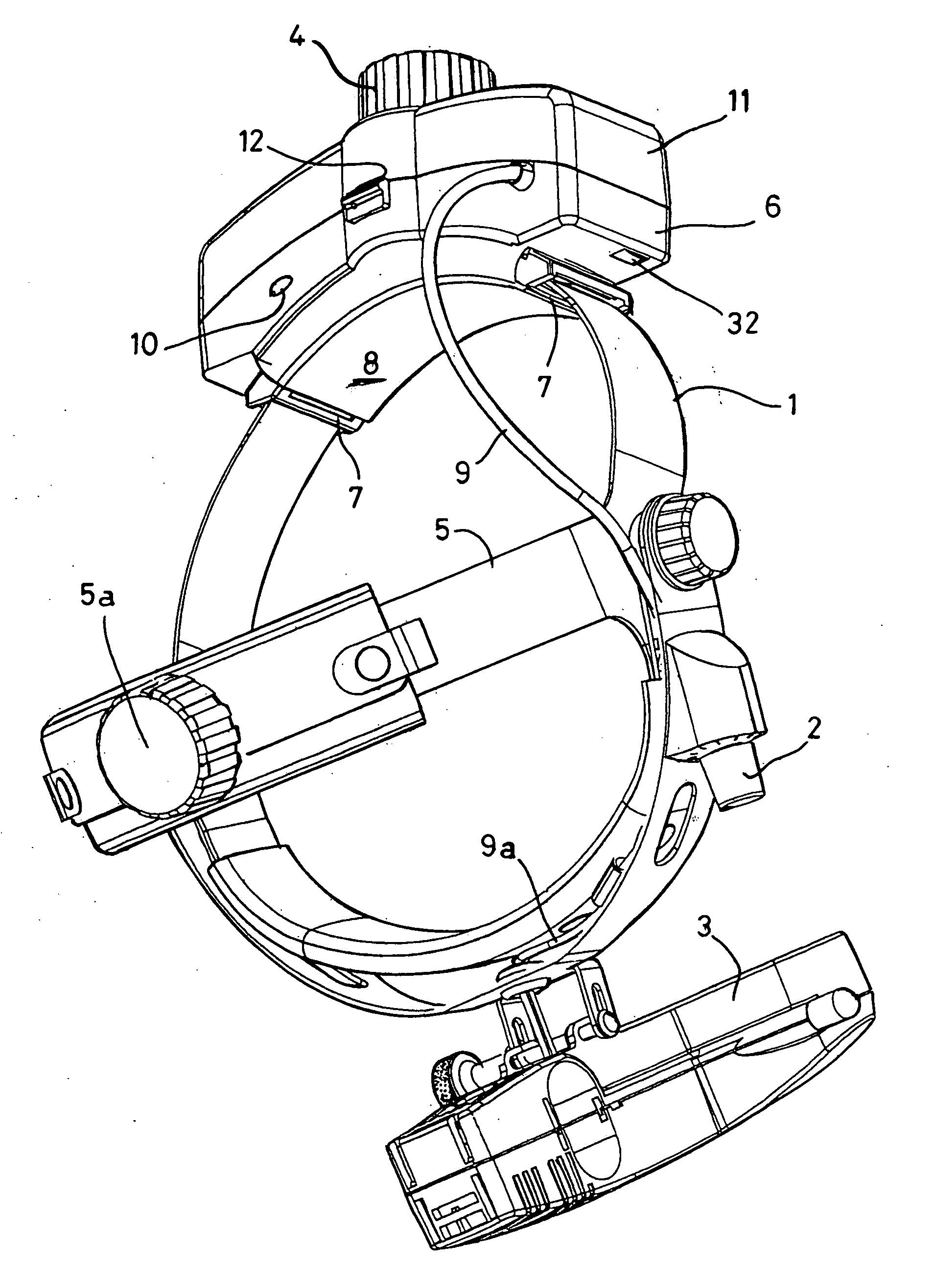
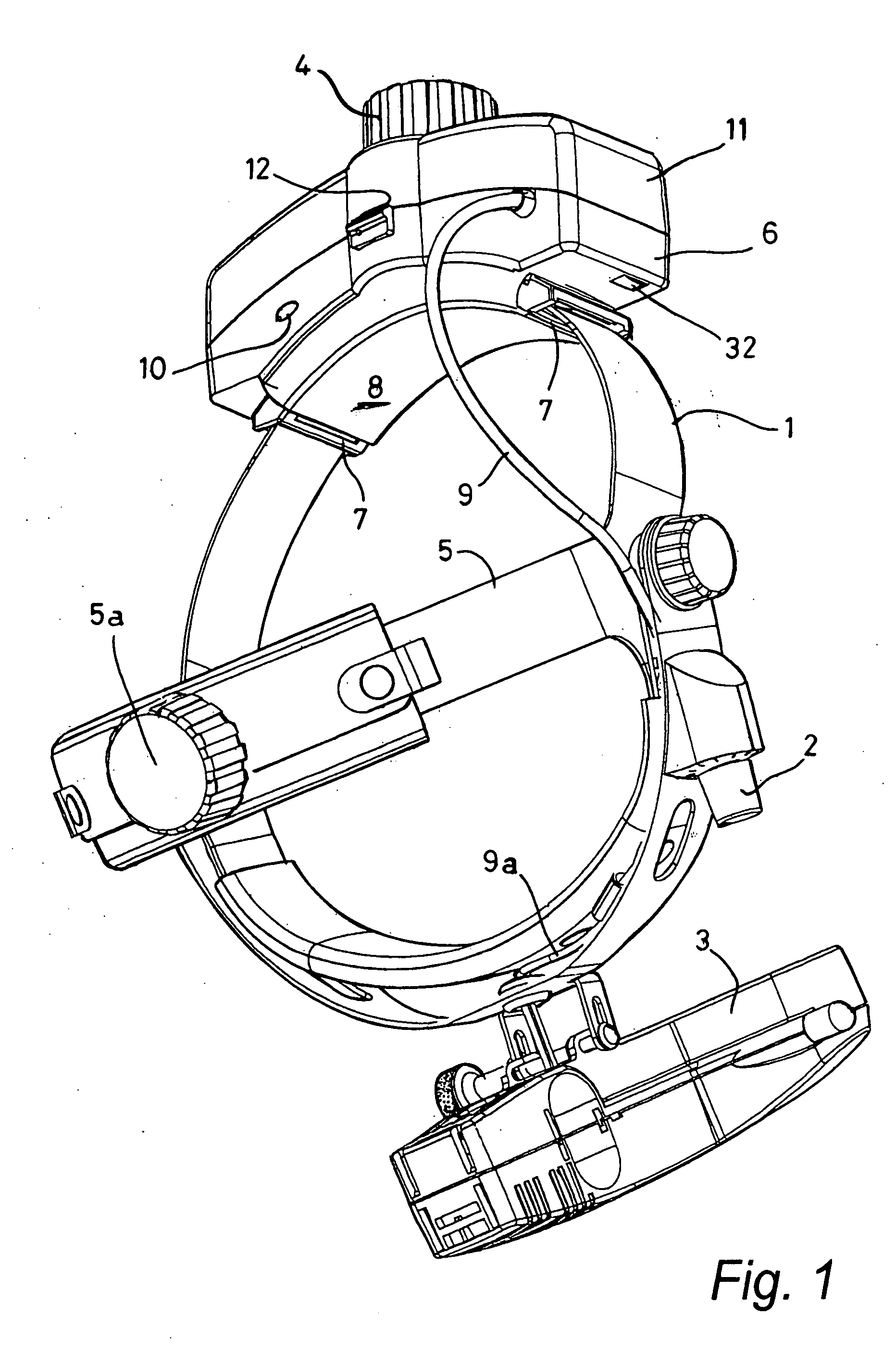
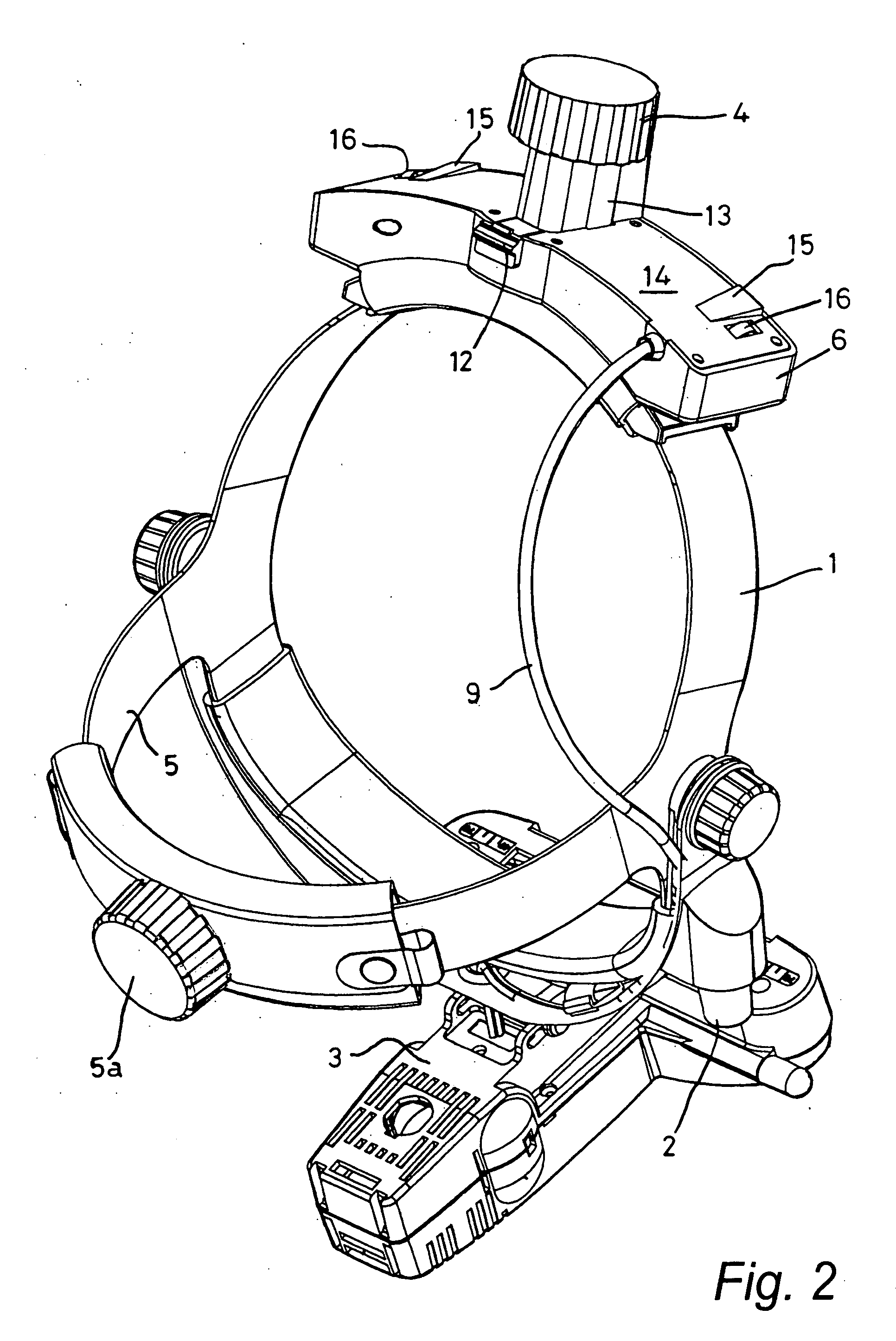
[0019] Referring to FIG. 1, the ophthalmoscope has a headband 1 the front region of which carries an ophthalmoscope unit 3 having a light source and optics for viewing an image of a patient's retina illuminated by the light source, the intensity of which is controllable by a control 2. The tension in the headband 1 is adjusted by adjustment means including a rotatably adjustable knob 4 which projects centrally from the ophthalmoscope at the rear thereof. An upper loop 5 extends from one side of the headband to the other and, in use, extends over the top of the wearer's head. An adjusting knob 5a controls the effective length of the loop 5.

[0020] To the rear of the headband is permanently attached a battery base unit 6 having slots 7 through which lengths of the headband 1 extend. Between the slots 7 the front surface 8 of the base unit 6 is concave, to fit snugly against the back of the wearer's head. An electrical wire 9 passes from the base unit 6 to the light control 2 and a lin...


PUM


Abstract

A head mounted instrument, such as an indirect ophthalmoscope, has an electrically powered instrument unit and a headband for carrying the instrument unit at or adjacent the front of the wearer's head. A manually adjustable member on the headband enables the effective size of the latter to be adjusted to suit the size of the wearer's head, and is located at the rear of the user's head when the headband is worn. Power for the instrument is provided by one or more electric batteries located or locatable on the headband such that the weight of the battery / batteries is centred substantially at the rear of the user's head when the headband is worn, the battery / batteries being supported or supportable on the headband through mounting formations so that the battery / batteries are supported or supportable on the headband other than through the intermediary of the adjustment member.

Description

FIELD OF THE INVENTION [0001] This invention relates to head-mounted instruments and particularly, but not exclusively, to head-mounted indirect ophthalmoscopes. BACKGROUND TO THE INVENTION [0002] A conventional head-mounted indirect ophthalmoscope comprises a headband a front region of which carries an ophthalmoscope unit and the rear of which has an adjustment knob for adjusting the effective size of the headband (e.g. by altering the tension in the headband) to suit the size of the wearer's head. The ophthalmoscope unit has a light source powered by a separate battery pack which can be mounted on the user's belt or a wall, or is alternatively powered by a wall-mounted mains electricity power supply. The ophthalmoscope unit also has image-receiving optics by which the user (e.g. doctor or optician) of the ophthalmoscope views a stereoscopic image of a patient's retina illuminated by the light from the light source. [0003] In one known head-mounted indirect ophthalmoscope, the adju...

Claims


Application Information

Patent Timeline
IPC IPC(8): A61B3/12F21V21/084
CPCF21V21/084A61B3/12
Inventor ATKINS, NEIL ANTHONYLAVELLE, MARK
Owner KEELER
Learn More