
Optical disk, optical disk apparatus, optical disk recording and reproduction method, and apparatus and method for recording BCA code

a technology of optical disk and optical disk, which is applied in the field of optical disk, optical disk apparatus, optical disk recording and reproduction method, and apparatus and methods for recording bca codes. it can solve the problems of long time required for disk discrimination, increased reading error of information, and decreased compatibility of optical disks

Inactive Publication Date: 2005-06-16
KK TOSHIBA
View PDF13 Cites 23 Cited by
  • Summary
  • Abstract
  • Description
  • Claims
  • Application Information

AI Technical Summary

Benefits of technology

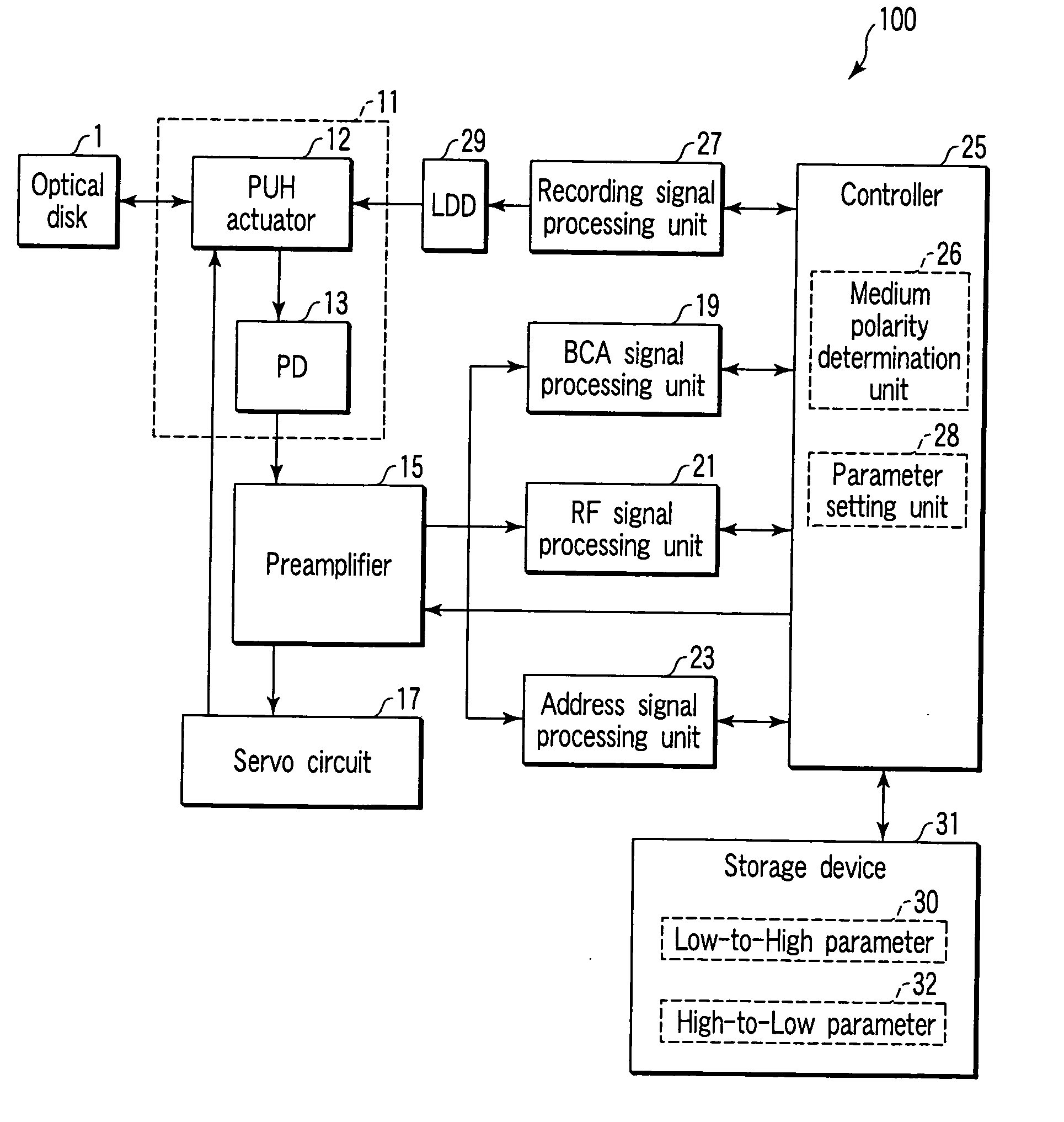
[0016] In accordance with an optical disk apparatus and an optical disk recording and reproduction method of an embodiment of the invention, regardless of whether the optical disk is the H-L medium or the L-H medium, the medium polarity determination is correctly performed and a parameter of a circuit is optimized in a lead-in area and a data area on the basis of the determination. When the polarity of the medium is changed, the reflectance of the optical disk and the like are largely changed in the lead-in area and the data area except the BCA. The optimization can perform the stable servo control and the correct information readout for any optical disk.

Problems solved by technology

When the optical disk having the signal polarity different from the H-L medium is reproduced with the conventional optical disk apparatus, there is a problem that compatibility of the optical disk is decreased, reading errors of the information are increased, or a long time is required for discrimination of the disk.
When the optical disks whose average levels of the signals are remarkably different from each other are mixed, it is necessary to broaden a pulling enabling range of a focus servo circuit in order to focus the light beam onto the optical disk, which results in the problem that design of the optical disk apparatus becomes difficult or cost is increased.

Method used


Image

  • Optical disk, optical disk apparatus, optical disk recording and reproduction method, and apparatus and method for recording BCA code
  • Optical disk, optical disk apparatus, optical disk recording and reproduction method, and apparatus and method for recording BCA code
  • Optical disk, optical disk apparatus, optical disk recording and reproduction method, and apparatus and method for recording BCA code

Examples


Embodiment Construction

[0033] Referring now to the accompanying drawings, preferred embodiments of the invention will be described in detail.

(Information Recording Medium of the Invention)

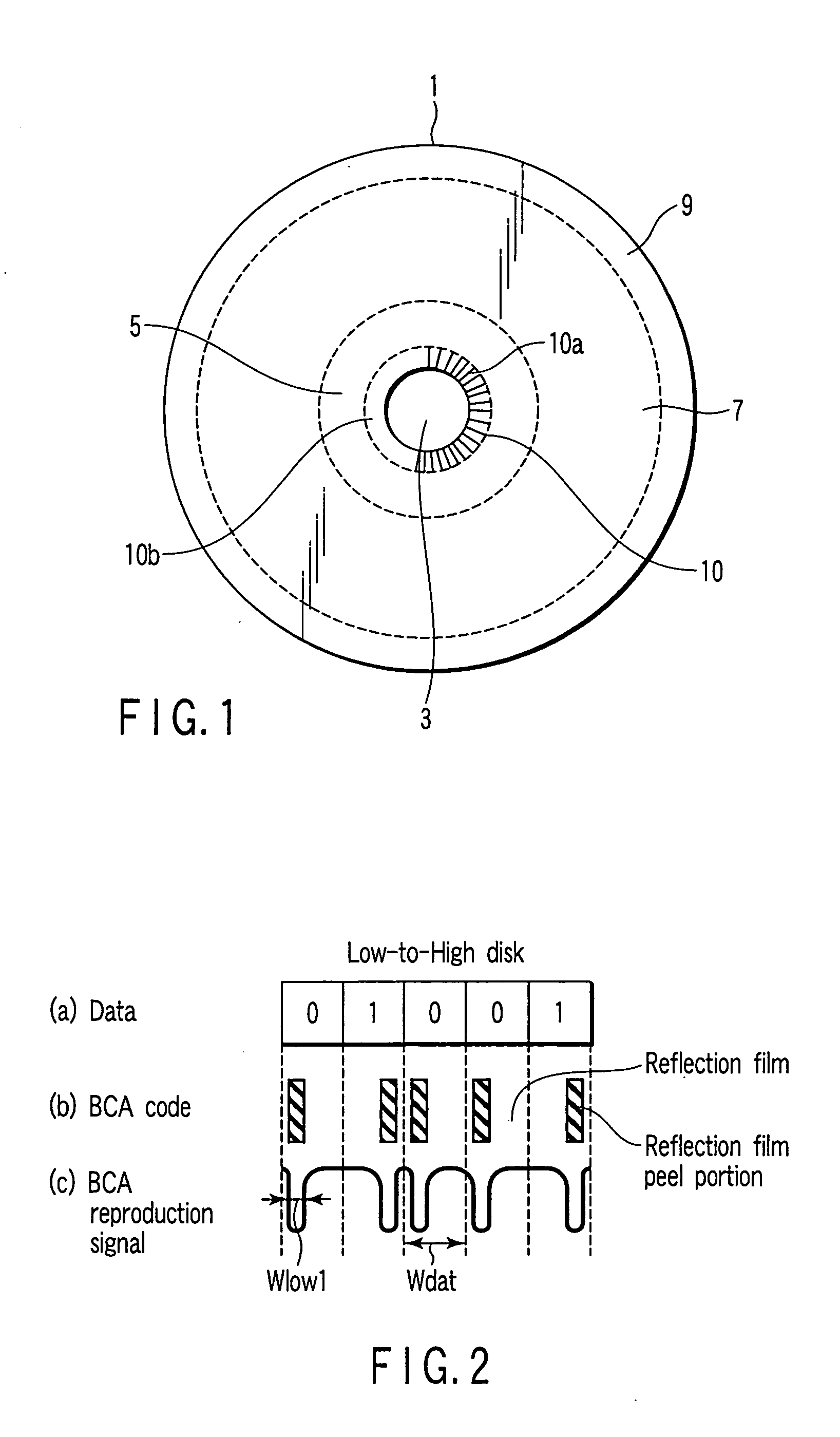
[0034]FIG. 1 shows a configuration of an information recording medium according to an embodiment of the invention. An information recording medium (optical disk) 1 of the invention has a clamp hole 3 for clamping in the center of the optical disk 1. An information recording layer of the optical disk 1 is divided into a plurality of zonal areas including a BCA 10, a lead-in area 5, a data area 7, and a lead-out area 9 in order from the inner radius of the optical disk 1. Widths and radius points of the disk of these areas are previously defined by the type of disk. At this point, a recording mark referred to as pre-pit is previously recorded by projections and depressions in a part of the lead-in area 5. Disk management information such as the type of disk and recommended strategy is stored in the pre-pit. Spiral groov...


PUM

PropertyMeasurementUnit
cut-off frequencyaaaaaaaaaa
reflectanceaaaaaaaaaa

Abstract

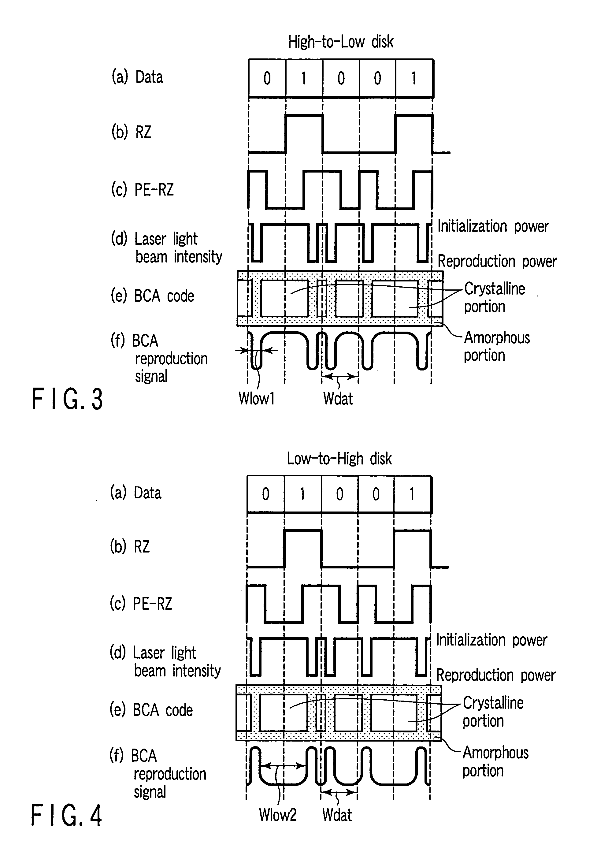
A disk has a burst cutting area (BCA) formed by a crystalline portion and an amorphous portion, and the disk is an optical disk (L-H medium) in which the reflectance of the crystalline portion is lower than that of the amorphous portion. The width Wcry of the crystalline portion in the BCA is lower than half the data period Wdat. Therefore, the average level of a BCA reproduction signal is unchanged regardless of whether the optical disk is an H-L medium or an L-H medium, so that focus control and reproduction of a BCA code can be performed even if a parameter of a circuit is a default.

Description

CROSS-REFERENCE TO RELATED APPLICATIONS [0001] This application is based upon and claims the benefit of priority from prior Japanese Patent Application No. 2003-400117, filed Nov. 28, 2003, the entire contents of which are incorporated herein by reference. BACKGROUND OF THE INVENTION [0002] 1. Field of the Invention [0003] The present invention relates to an information recording medium (optical disk) having a burst cutting area (BCA), an optical disk apparatus using the BCA, an optical disk recording and reproduction method, and an apparatus and method for recording a BCA code. [0004] 2. Description of the Related Art [0005] As is well known, recently an optical disk having a storage capacity of 4.7 GB in single-sided one-layer format has become commercially practical as an optical disk on which information can be recorded with high density. For example, the practically used optical disks include DVD-ROM (Digital Versatile Disk Read-Only Memory) which is of a read-only optical disk...

Claims


Application Information

Patent Timeline
Patent Type & Authority Applications(United States)
IPC IPC(8): G11B5/09G11B7/00G11B7/004G11B7/0045G11B7/005G11B7/007G11B7/085G11B7/125G11B7/24G11B7/26G11B20/10G11B20/12
CPCG11B7/268G11B7/00736G11B7/007
Inventor OGAWA, AKIHITONAKAMURA, NAOMASAOOMACHI, NORITAKEYUSU, KEIICHIRO
Owner KK TOSHIBA
Learn More