Receiver, receiving method, reception controlling program, and recording medium

a technology of receiving method and recording medium, applied in the direction of multiplex communication, orthogonal multiplex, polarisation/directional diversity, etc., can solve problems such as errors in demodulation

Inactive Publication Date: 2005-06-16
PIONEER CORP
View PDF4 Cites 59 Cited by
  • Summary
  • Abstract
  • Description
  • Claims
  • Application Information

AI Technical Summary

Problems solved by technology

One of the possible problems is that when distortion ascribable to multipath, fading, and the like occurs in the transmission channel and the radio waves are received with degradation at certain frequencies, the results of demodulation can involve errors even if the desired wave has sufficient reception power as a whole.

Method used


Image

  • Receiver, receiving method, reception controlling program, and recording medium
  • Receiver, receiving method, reception controlling program, and recording medium
  • Receiver, receiving method, reception controlling program, and recording medium

Examples


first embodiment

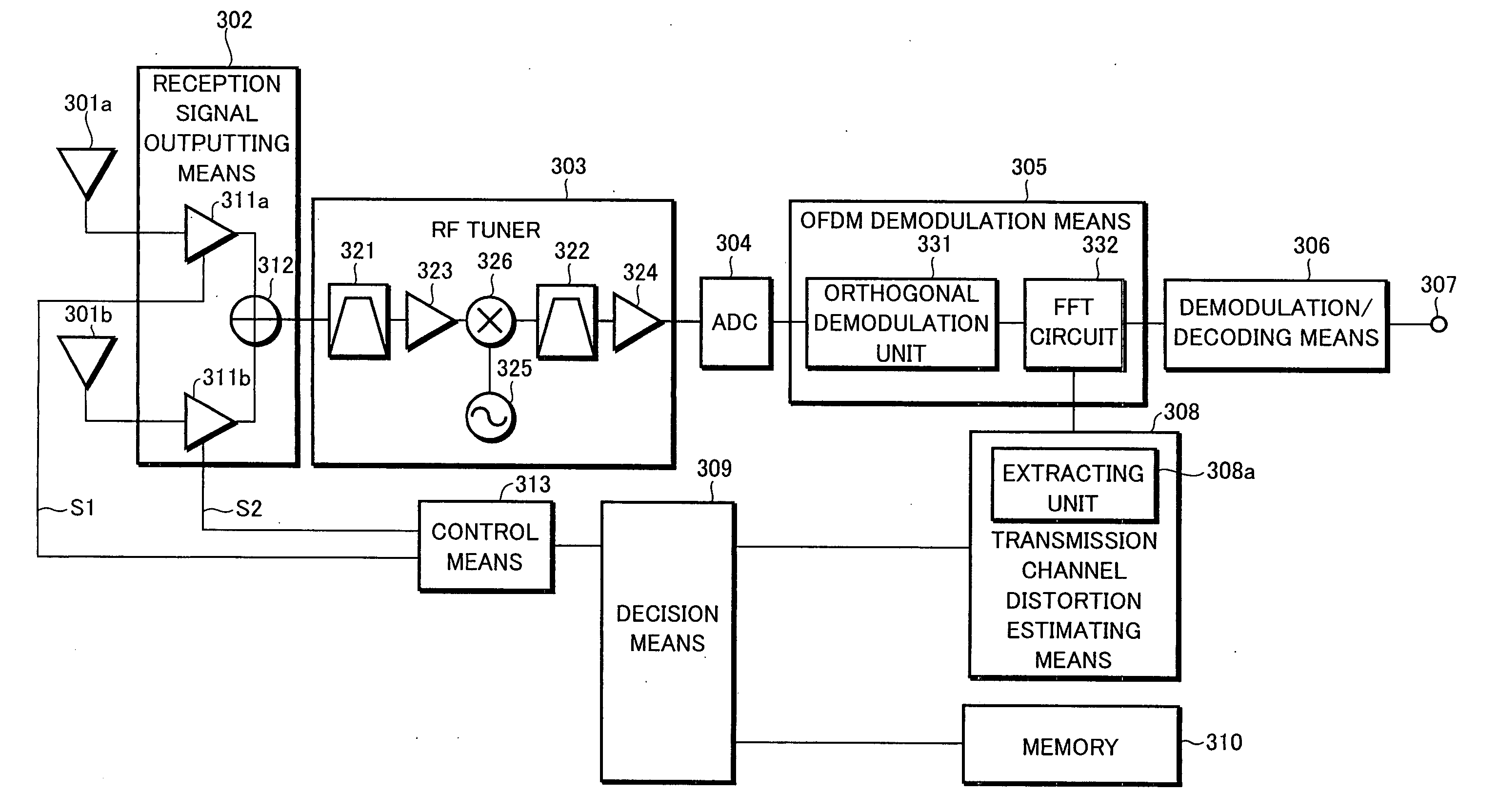
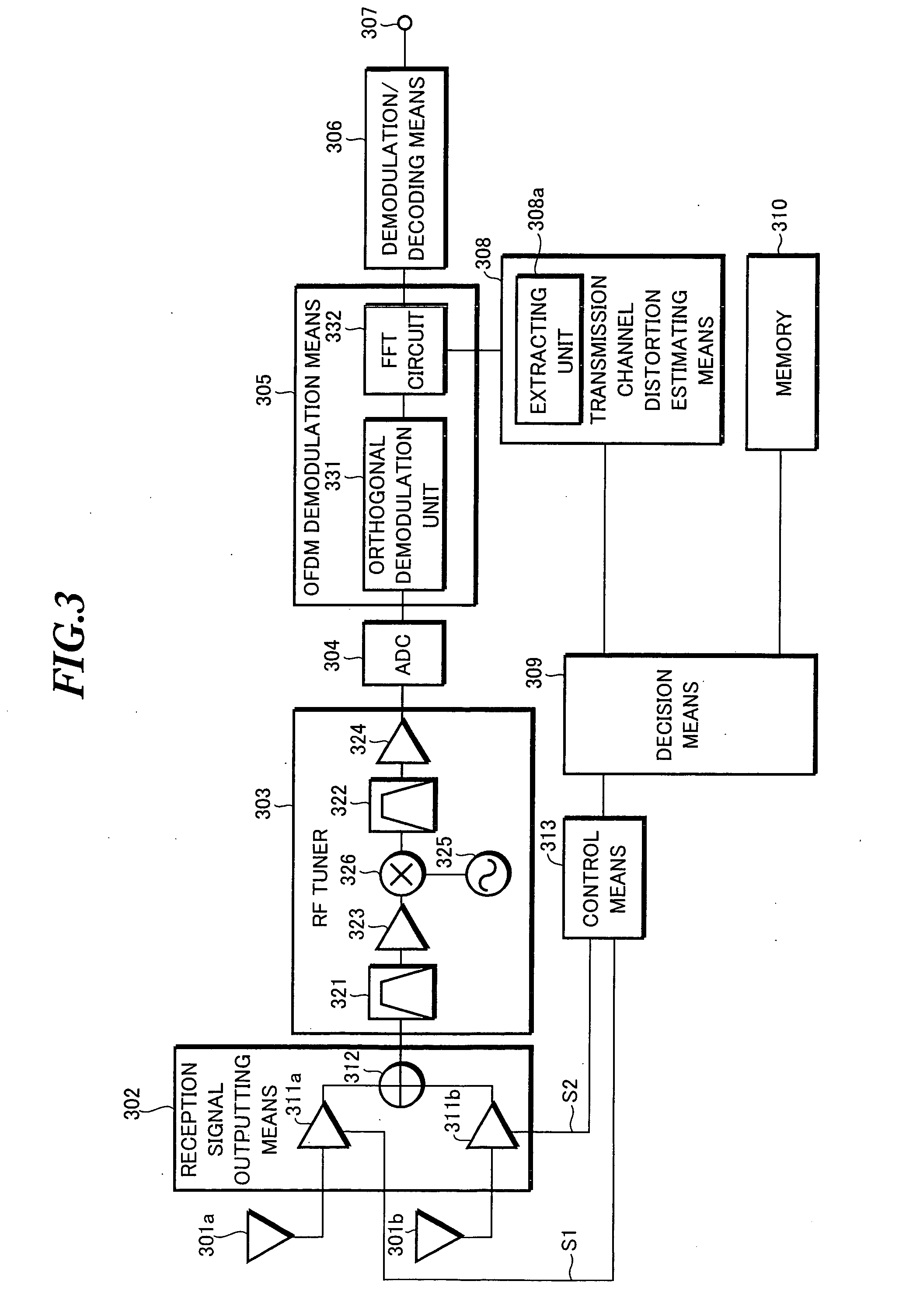
[0026] Now, a first embodiment of this invention will be described. FIG. 3 is a block diagram showing the general configuration of a receiver according to the first embodiment.

[0027] The transmission signal under the OFDM transmission scheme is received by a plurality of antennas 301a and 301b. For diversity reception, the number of antennas is at least two. Reception signal outputting means 302 selects the transmission signal received by the antenna 301a or 301b which is selected based on select signals S1 and S2 of decision mean 309, and outputs the same to an RF tuner 303. This reception signal outputting means 302 comprises AGC amplifiers 311a and 311b, and an adding unit 312. The gain of the AGC amplifier 311a or 311b which is provided for the antenna 301a or 301b unselected by the select signals S1 and S2 is lowered to interrupt the input, or to decrease the proportion in the combining ratio of the transmission signals in the adding unit 312. The reception signal output means...

example 1

[0034] The memory 310 according to an example 1 contains a reference value for an SP carrier power difference of the pilot signals SP to be compared with. This SP carrier power difference is the differential power H−L between the pilot signals H of higher power and the pilot signals L of lower power among the pilot signals SP of the respective frequencies shown in FIG. 4. In the shown example, the group of pilot signals H of higher power include SP1-SP3 and SP7-SPn. The group of pilot signals L of lower power include SP4-SP6.

[0035] The decision means 309 compares the differences between the frequency-specific powers of the pilot signals extracted by the transmission channel distortion estimating means 308 and the reference value stored in the memory 310. If the differences between the frequency-specific powers of the pilot signals exceed the reference value, or threshold, the resulting decision to switch the antennas 301a and 301b selectively is output to the control means 313. The...

example 2

[0046] An example 2 provides a configuration in which the processing of the example 1 described above is performed in units of a plurality of symbols. FIG. 7 is a flowchart for explaining the operation of changing the receiving condition according to the example 2. As employed in the processing shown in FIG. 7, the parameter n represents the number of symbols of the pilot signals SP to be used for deciding on the operation of changing the receiving condition. The parameter m represents the number of symbols of the pilot signals SP stored in the memory 310. This m has an initial value of zero.

[0047] When a transmission signal is received, the individual components shown in FIG. 3 perform signal processing on this transmission signal. A signal is thus demodulated by the FFT circuit 332 of the OFDM demodulation means 305. The extracting unit 308a extracts a pilot signal SP from the signal demodulated by the OFDM demodulation means 305 (step S701). Next, the extracted pilot signal SP i...


PUM


Abstract

An RF tuner tunes received transmission signal to an OFDM signal of a desired wave and converts the same into intermediate frequencies. After digital conversion in an ADC, an OFDM demodulation unit obtains a demodulated-wave symbol signal of the orthogonal frequency signal. A transmission channel distortion estimating unit extracts pilot signals and estimates distortion of a transmission channel. A decision unit compares the distortion of the transmission channel estimated and a reference value stored in a memory, and outputs the result of comparison to the control unit, thereby switching antennas selectively. Thus, the receiver always selects an optimum receiving condition in a manner adaptive to variations in the state of reception of the transmission signal and the characteristics of the receiver such as the modulation method of the transmission signal received.

Description

BACKGROUND OF THE INVENTION [0001] The present invention relates to a receiver, a receiving method, a reception controlling program, and a recording medium. [0002] The present application claims priority from Japanese Patent Application No. 2003-414834, the disclosure of which is incorporated herein by reference. [0003] In recent years, terrestrial digital broadcasting has adopted orthogonal frequency division multiplexing (OFDM) which is resistant to multipath and fading. To receive this terrestrial digital broadcasting on movable bodies such as a vehicle with stability, some receivers adopt diversity reception techniques for switching a plurality of antennas as appropriate (for example, see Japanese Patent Application Laid-Open No. 2003-143100). [0004] In the conventional technology described above, however, the diversity operation for switching antennas is performed based on the reception power of the entire desired wave included in the received radio waves. One of the possible p...

Claims


Application Information

Patent Timeline
Patent Type & Authority Applications(United States)
IPC IPC(8): H04B7/08H04J11/00H04L27/26
CPCH04B7/0814H04L27/2647H04B7/0842
Inventor HOSHINO, HIRONOBU
Owner PIONEER CORP
Why Eureka
Try Eureka