Diagnostic table
a technology of diagnostic table and cylinder head, applied in the field of diagnostic table, can solve the problems of leaking oil for the reduction gear(s), affecting the operation of the reduction gear, and the inability of the magnetic brake to support the weight,
- Summary
- Abstract
- Description
- Claims
- Application Information
AI Technical Summary
Benefits of technology
Problems solved by technology
Method used
Image
Examples
first case
(First Case)
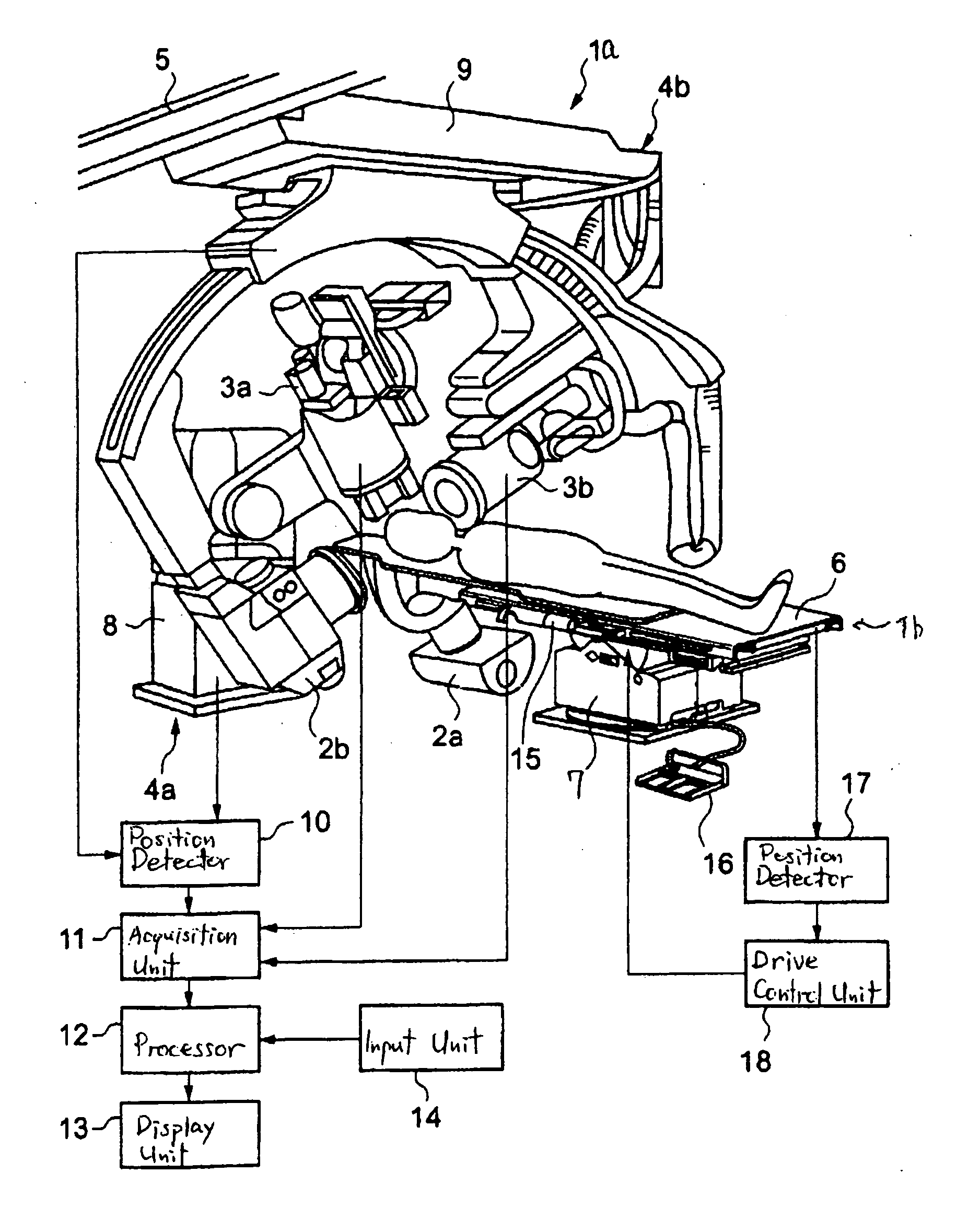
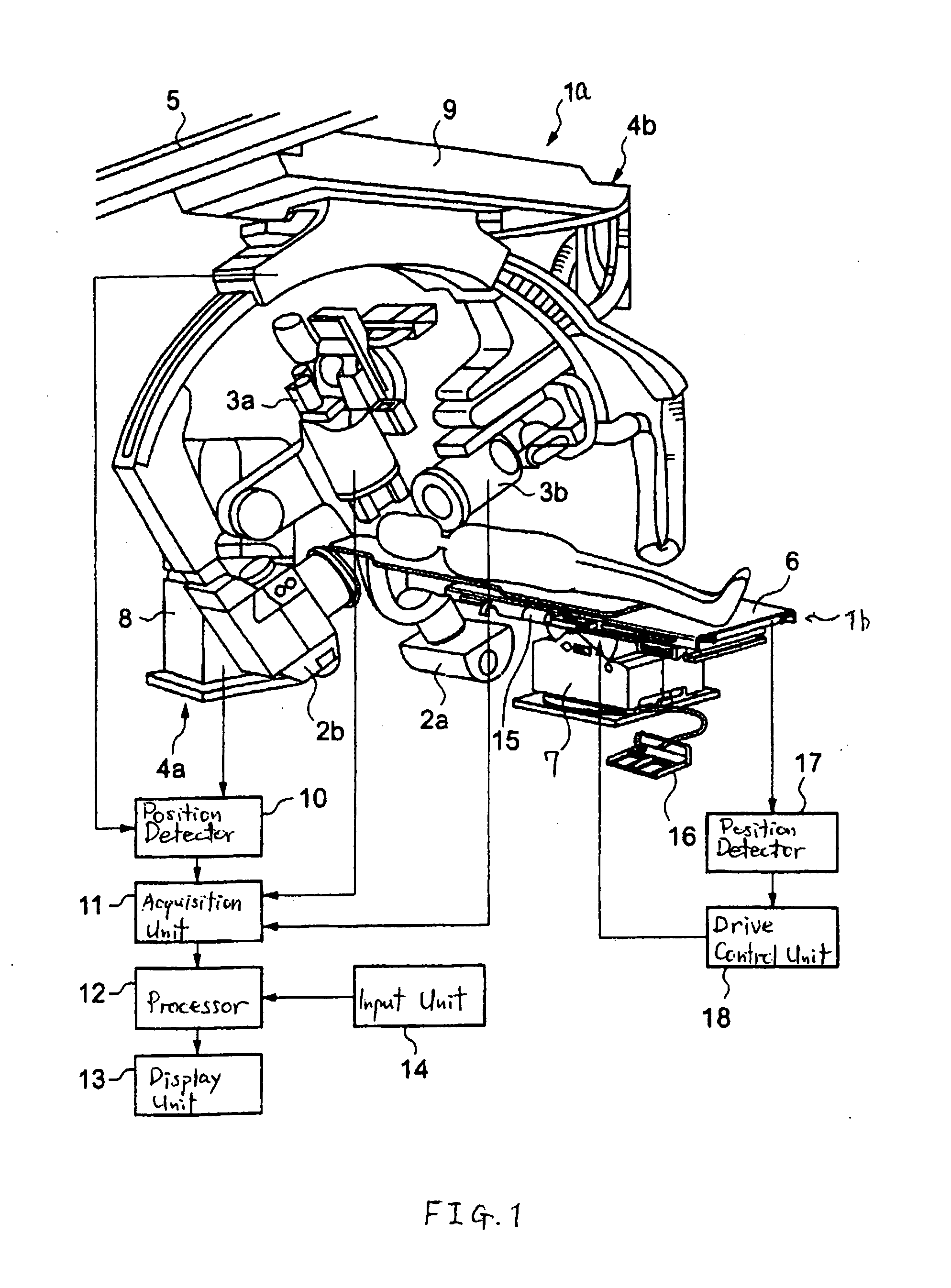
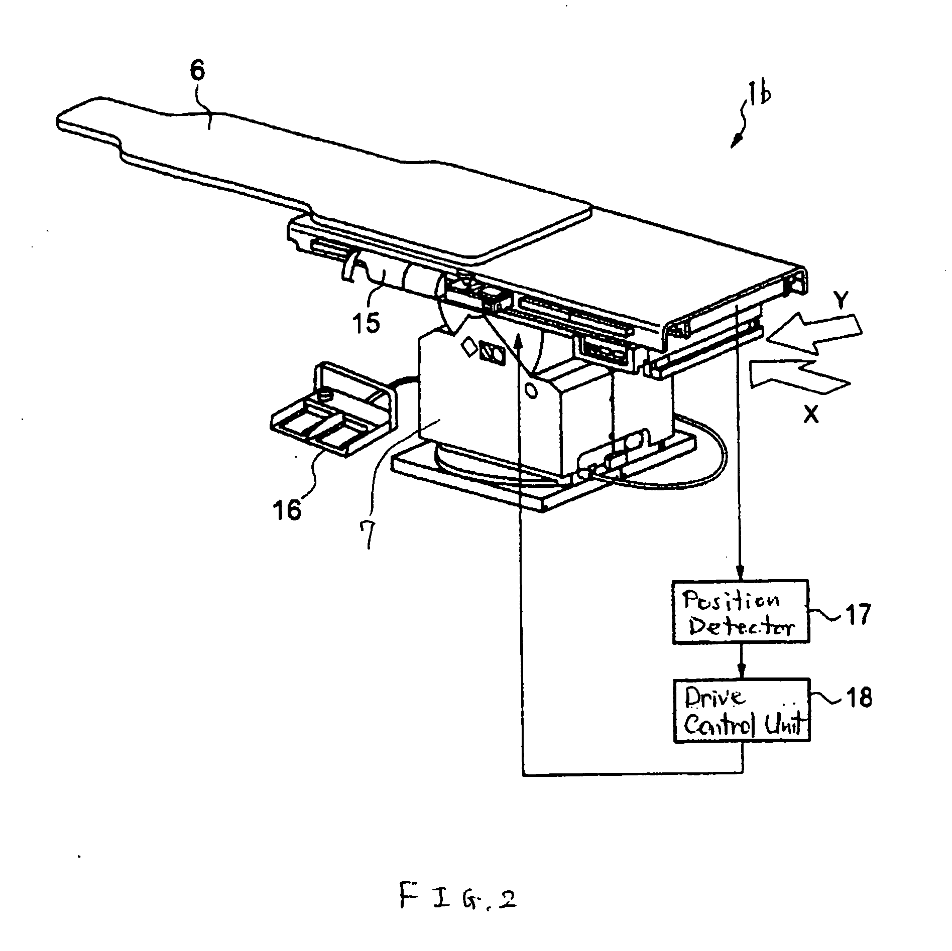
[0056] When the tabletop 6 starts to slide in the direction C′, the potentiometer 20 and the encoder 21 detect a certain amount of movement of the tabletop 6. The detected amount is provided to the drive control unit 18. The drive control unit 18 determines whether any instruction is received or not from the operation unit 15 to move the tabletop 6 along the direction C. In other words, the drive control unit 18 determines whether or not to activate the gear motor 19 in response to the operation unit 15 or any other proper instruction.
[0057] If the drive control unit 18 has determined that no instruction is received or no activation instruction is made, the drive control unit 18 controls the solenoid 7c to move the movable iron core 7d towards the tabletop 6 (in a direction F′).
[0058] The solenoid 7c provides a predetermined voltage to the excitation coil (not shown) to generate a magnetic force which can linearly move the movable iron core 7d. The movable iron core 7d...
second case
(Second Case)
[0060] When the tabletop 6 starts to slide in the direction C′, the potentiometer 20 and the encoder 21 detect a certain amount of movement of the tabletop 6. The detected amount is provided to the drive control unit 18. The potentiometer 20 and the encoder 21 can also detect information of direction of such amount of movement. If the drive control unit 18 has determined that an instruction is received from the operation unit 15 or an activation instruction is given to the gear motor 19 in order to move the tabletop 6 along the longitudinal direction C but not in the direction C′, the drive control unit 18 controls the solenoid 7c to protrude or extend or extend the movable iron core in the direction F′.
[0061] In this case, the instruction is given to move the tabletop 6 upwards along the longitudinal direction C, that is, in a direction opposite to the direction C′. Since the one end L of the tabletop 6 is lifted while the other end R is lowered, the tabletop 6 slides...
third case
(Third Case)
[0062] When the tabletop 6 starts to slide in the direction C′, the potentiometer 20 and the encoder 21 detect a certain amount of movement of the tabletop 6. The detected amount is provided to the drive control unit 18. The potentiometer 20 and the encoder 21 can also detect information of direction of such amount of movement. Even if the drive control unit 18 has determined that an instruction is received from the operation unit 15 or an activation instruction is given to the gear motor 19 in order to move the tabletop 6 along the longitudinal direction C and in the direction C′, the drive control unit 18 may determine to control the solenoid 7c to protrude or extend the movable iron core in the direction F′.
[0063] For example, when a rotation speed of the gear motor 19 is predetermined or determined in response to an instruction from the operation unit 15, the drive control unit 18 instructs the gear motor 19 to rotate at the determined rotation speed when or before ...
PUM
 Abstract
Description
Claims
Application Information
 - R&D
- Intellectual Property
- Life Sciences
- Materials
- Tech Scout
- Unparalleled Data Quality
- Higher Quality Content
- 60% Fewer Hallucinations
Browse by: Latest US Patents, China's latest patents, Technical Efficacy Thesaurus, Application Domain, Technology Topic, Popular Technical Reports.
© 2025 PatSnap. All rights reserved.Legal|Privacy policy|Modern Slavery Act Transparency Statement|Sitemap|About US| Contact US: help@patsnap.com


