Variable displacement vane pump with variable target reguator

Inactive Publication Date: 2005-06-16
SLW AUTOMOTIVE
View PDF97 Cites 17 Cited by
  • Summary
  • Abstract
  • Description
  • Claims
  • Application Information

AI Technical Summary

Benefits of technology

[0007] A lubricant pumping system for providing lubrication to an engine or an apparatus having a variable speed-rotating shaft. The lubricant system includes a first lubricant pump having variable displacement that is variably adjustable in response to a control input. A second fixed displacement pump is operably connected to a rotating shaft of the engine to pro

Problems solved by technology

A fixed displacement pump operating at high speeds and at cold start conditions can produce excessively high oil pressures, and at high temperature and low speed conditions the oil pressure can be less than desired.
Increasing the d

Method used


Image

  • Variable displacement vane pump with variable target reguator
  • Variable displacement vane pump with variable target reguator
  • Variable displacement vane pump with variable target reguator

Examples


Embodiment Construction

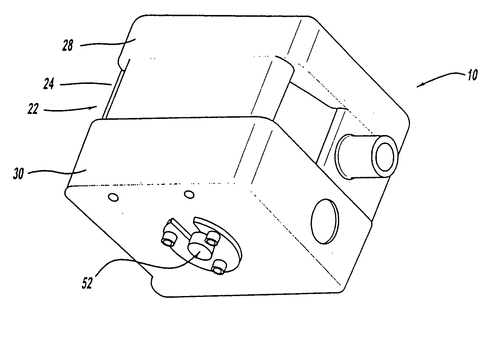
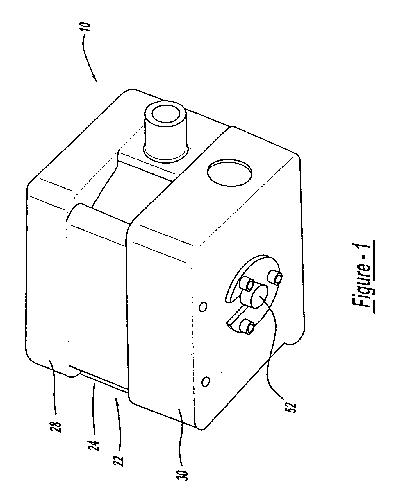
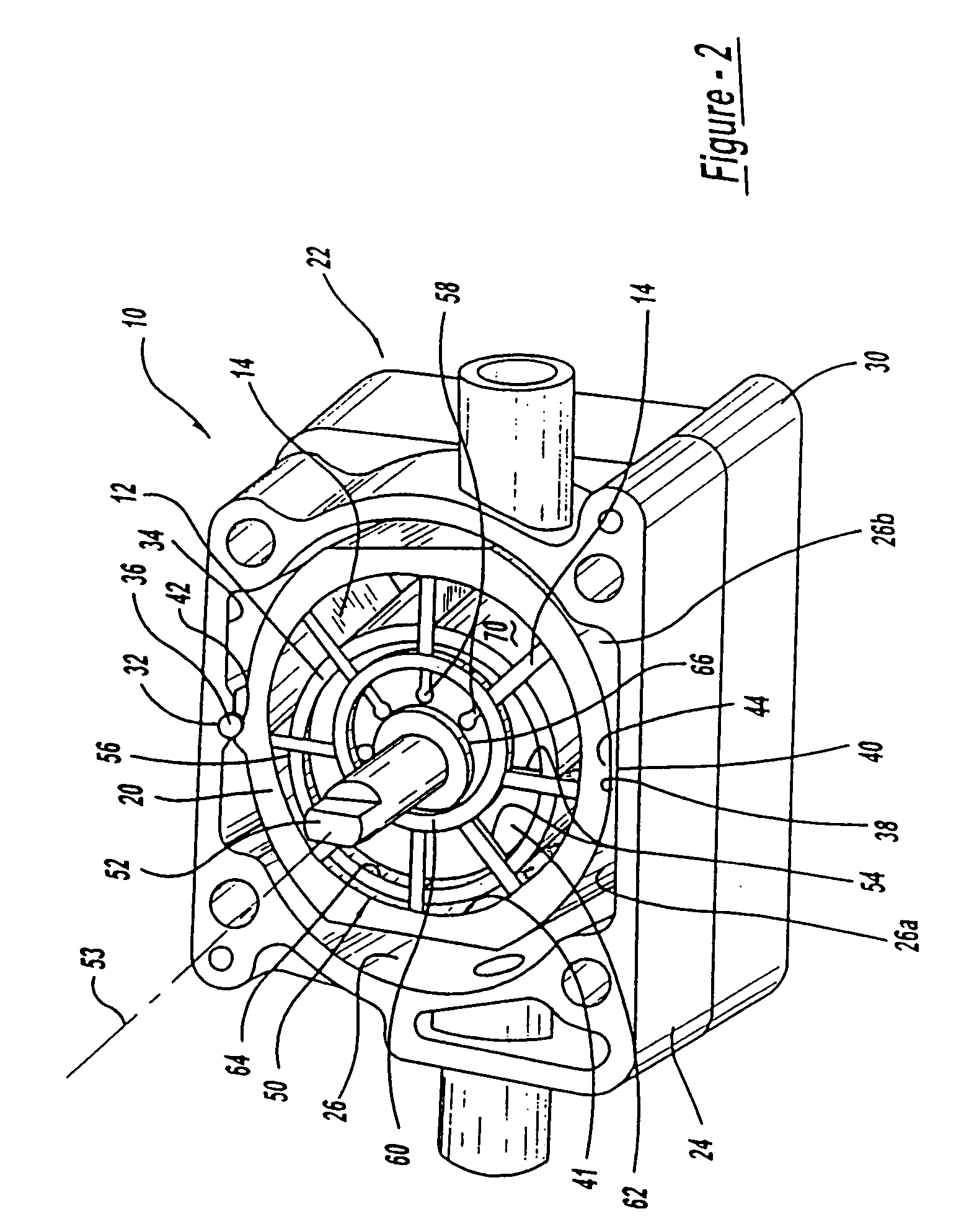
[0028] Referring in more detail to the drawings, FIGS. 1-3 illustrate a variable displacement vane pump 10 having a rotor 12 and associated vanes 14 driven for rotation to draw fluid through a pump inlet 16, increase the pressure of the fluid, and discharge the fluid under pressure from an outlet 18 of the pump 10. A containment ring or eccentric ring 20 is carried by a housing 22 of the pump 10 and is pivoted relative to the rotor 12 to vary the displacement of the pump. Such a pump 10 is widely used in a plurality of fluid applications including engine lubrication and power transmission applications.

[0029] The housing 22 preferably comprises a central body 24 defining an internal chamber 26 in which the containment ring or eccentric ring 20 and rotor 12 are received. The housing 22 further includes a pair of end plates 28, 30 on opposed, flat sides of the central body 24 to enclose the chamber 26. A groove 32 formed in an internal surface 34 of the central body 24 is constructed ...


PUM


Abstract

A variable displacement vane-type fluid pump is provided which permits improved regulation of the pump discharge such that the pump can meet the various requirements of lubrication for internal combustion engines at all speeds with minimized use of power. Of course, the vane pump may also be utilized in a wide range of power transmission and other fluid distribution applications. The vane pump of the invention may also use both hydrostatic and mechanical actuators to control the position of its containment ring or eccentric ring and hence, regulate the output of the pump. According to yet another aspect of the present invention, to prevent inlet flow restriction or cavitation, a valve may be provided to permit some of the pump outlet or discharge flow to bleed into the pump inlet to provide needed velocity energy to the fluid flow into the pump inlet. A system for lubrication of an engine using a fixed displacement pump for providing an engine speed input for controlling a second main variable displacement type oil pump and maintaining a target oil pressure in the oil pressure circuit. A solenoid valve is used for venting output of the fixed displacement pump to create a second target oil pressure characteristic or curve when desired.

Description

CROSS-REFERENCE TO RELATED APPLICATION [0001] This application claims the benefit of U.S. Provisional Patent Application Ser. No. 60 / 510,222, filed Oct. 10, 2003, titled “Variable Displacement Vane Pump With Variable Target Regulator,” and is a continuation-in-part of U.S. application Ser. No. 10 / 192,578, filed Jul. 10, 2002, titled “Variable Displacement Vane Pump with Variable Target Regulator,” which claims the benefit of U.S. Provisional Patent Application Ser. No. 60 / 304,604, filed Jul. 11, 2001, titled “Variable Displacement Hydraulic Pump System With a Variable Target Regulation Valve Subsystem,” and is a continuation-in-part of U.S. patent application Ser. No. 10 / 021,566, filed Dec. 12, 2001, titled “Variable Displacement Vane Pump with Variable Target Regulator,” which claims the benefit of U.S. Provisional Patent Application Ser. No. 60 / 255,629, filed Dec. 12, 2000, titled “Variable Displacement Pump and Method,” the entire specifications of all of which are expressly inco...

Claims


Application Information

Patent Timeline
IPC IPC(8): F01M1/02F01C11/00F01C21/08F01M1/16F01M1/20F04C2/10F04C2/344F04C11/00F04C14/22F04C14/26F16N13/20
CPCF01C11/002F01C21/0836F01C21/0863F01M1/16F01M2005/008F01M2011/021F16N13/20F04C2/102F04C2/3442F04C14/226F04C14/26F04C2270/18F01M2250/64
Inventor HUNTER, DOUGLAS G.HAASE, THOMAS
Owner SLW AUTOMOTIVE
Why Eureka
Try Eureka