
Fuel cell system for low pressure operation

a fuel cell and low-pressure technology, applied in the field of low-pressure fuel cells, can solve the problems of large, heavy, and relatively complex overall systems that have evolved, and can not meet stack outputs in the tens or hundreds of watts, and small-scale systems of this design are too heavy for many small applications

Inactive Publication Date: 2005-06-16
HYENERGY SYST
View PDF55 Cites 31 Cited by
  • Summary
  • Abstract
  • Description
  • Claims
  • Application Information

AI Technical Summary

Problems solved by technology

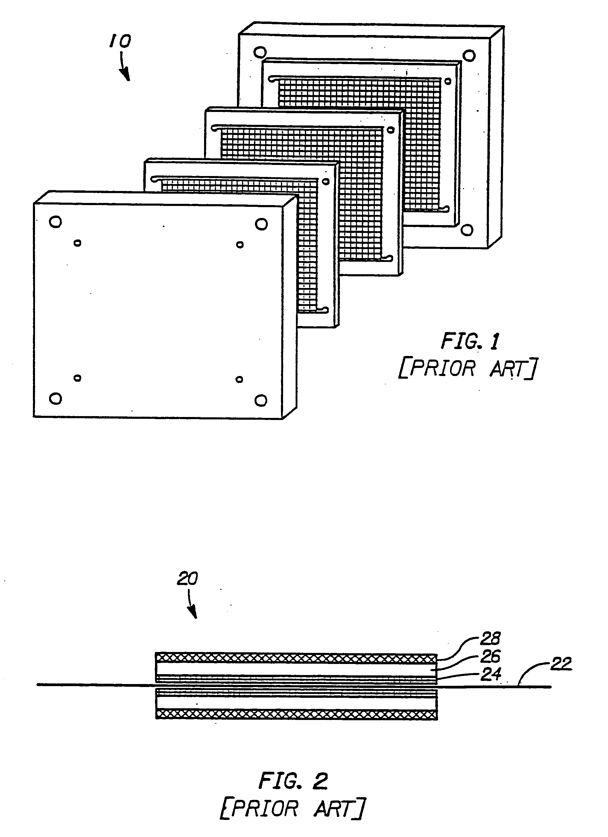
While improvements in the filter press style fuel cells have provided significant increases in power per unit volume, the overall systems that have evolved are large, heavy, and relatively complex, with compressors to supply air and pumps to provide forced water cooling systems to remove excess heat.
However, these systems are not well suited for stack outputs in the tens or hundreds of watts, since the rotating components, such as pumps and compressors, do not scale down well.
As a result, even small scale systems of this design are too heavy for many small applications, such as for portable applications and personal use.
Efforts to adapt the standard bipolar filter press design to low pressure operation, thereby eliminating much of the ancillary equipment, have met with some limited success, producing stacks with power densities as high as 61 W / lb.
While this is a useful power density, these systems require complicated and expensive assembly.
Second, they have a much higher energy density than hydrogen.

Method used


Image

  • Fuel cell system for low pressure operation
  • Fuel cell system for low pressure operation
  • Fuel cell system for low pressure operation

Examples


example 1

[0122] This example illustrates a gas diffusion electrode using carbon powder as the conductive material in the metal supported matrix.

[0123] A gas diffusion electrode was made by mixing Vulcan XC-72R high surface area carbon powder (available from CABOT Technology Division, Pampa, Tex.) with polytetrafluoroethylene “PTFE” suspension (such as T-30, available from DuPont, Wilmington Del.) in a 60:40 ratio (based on the dry weight of the PTFE), water, and a nonionic surfactant (such as Triton X100, available from Fisher Scientific, Fair Lawn, New Jersey). The carbon / PTFE mixture was sonicated to reach complete dispersion and the resulting paste was spread onto an expanded foil grid. This grid, fabricated from expanded copper foil, had previously been electroplated with a protective gold layer, through the use of a standard commercial gold electroplating both (E-56, from Engelhard, Corp., Iselin, N.J.) and serves as the grid to form a gas diffusion electrode.

[0124] The bulk of the wa...

example 2

[0125] This example illustrates a gas diffusion electrode using carbon fiber with carbon powder in the metal supported matrix.

[0126] The gas diffusion electrode was made by mixing Vulcan XC-72R high surface area carbon powder (CABOT) and Thornel™ DKD-X carbon fiber (Amoco Corp., Apharetta, Ga.) with PTFE suspension (T-30, DuPont), in a 52:17:31 ratio (based on the dry weight of the PTFE), water, and nonionic surfactant (Triton X100). The carbon / PTFE mixture was sonicated and fabricated into a metal supported gas diffusion electrode as described in example 1.

example 3

[0127] This example illustrates a gas diffusion electrode using carbon fiber with carbon powder in the metal supported matrix.

[0128] The gas diffusion electrode was made by mixing Vulcan XC-72R high surface area carbon powder (CABOT) and carbon fiber obtained by ball milling Toray TGP-H paper (Toray Corp., New York, N.Y.) with PTFE suspension (T-30, DuPont), in a 42:17:41 ratio (based on the dry weight of the PTFE), water, and nonionic surfactant (Triton X100). The carbon / PTFE mixture was sonicated and fabricated into a metal supported gas diffusion electrode as described in example 1.


PUM

PropertyMeasurementUnit
pressureaaaaaaaaaa
poweraaaaaaaaaa
pressureaaaaaaaaaa

Abstract

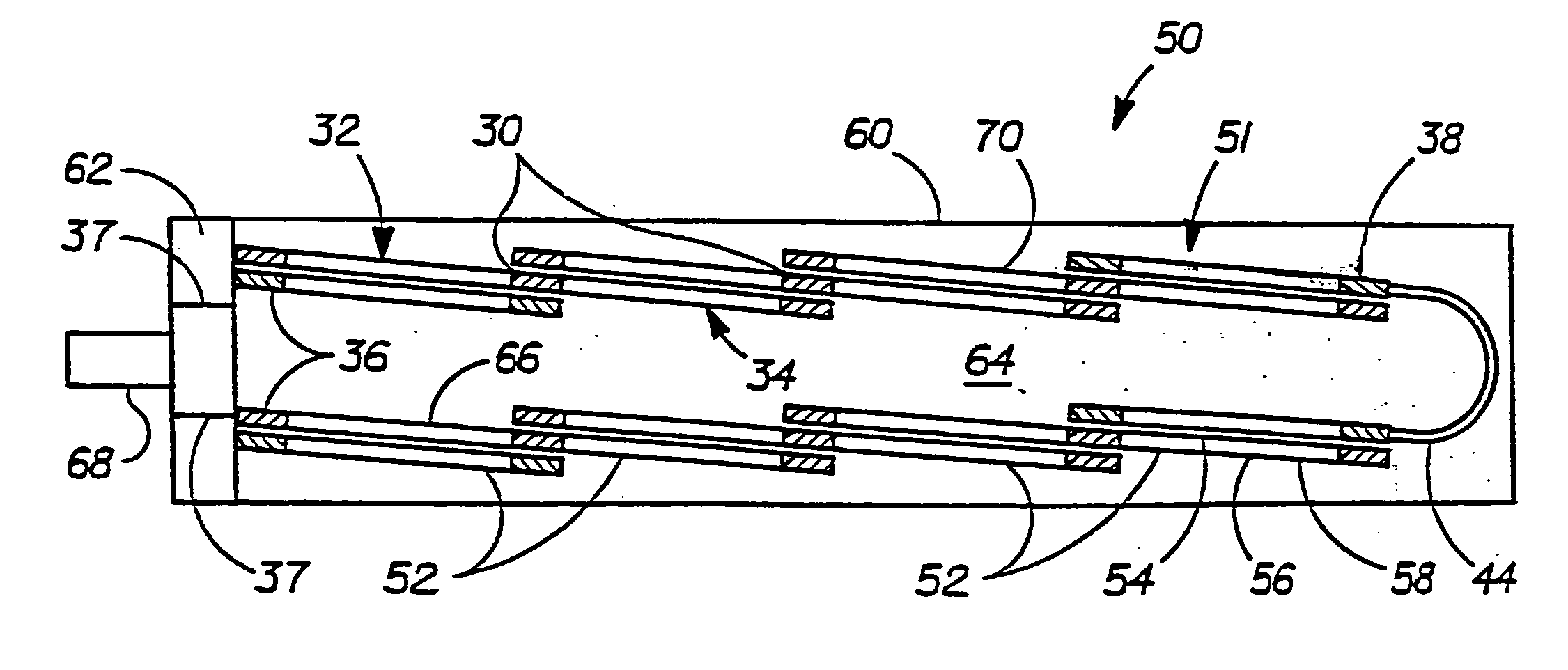
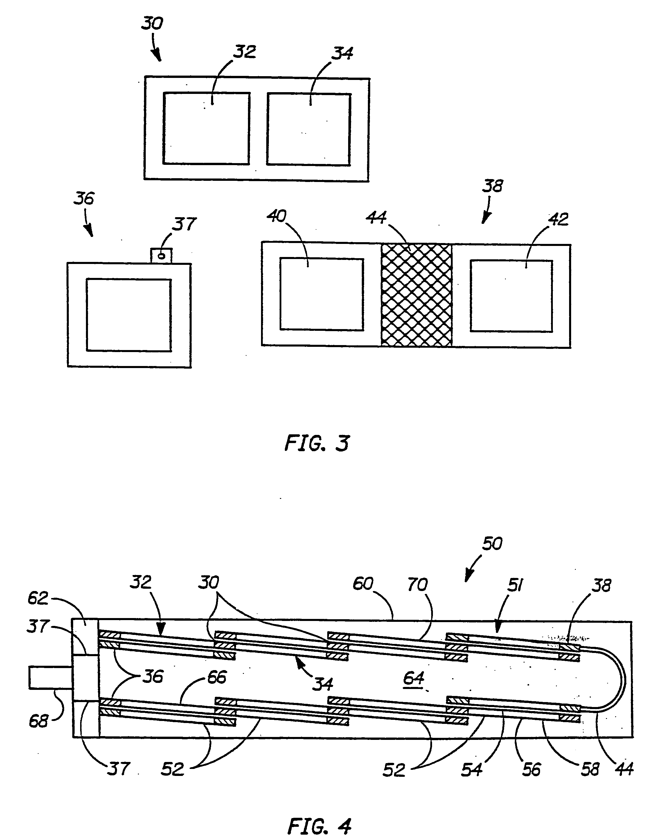
This invention is an improved fuel cell design for use at low pressure. The invention has a reduced number of component parts to reduce fabrication costs, as well as a simpler design that permits the size of the system to be reduced at the same time as performance is being improved. In the present design, an adjacent anode and cathode pair are fabricated using a common conductive element, with that conductive element serving to conduct the current from one cell to the adjacent one. This produces a small and simple system suitable for operating with gas fuels or alternatively directly with liquid fuels, such as methanol, dimethoxymethane, or trimethoxymethane. The use of these liquid fuels permits the storage of more energy in less volume while at the same time eliminating the need for handling compressed gases which further simplifies the fuel cell system. The electrical power output of the design of this invention can be further increased by adding a passage for cooling the stack through contact with a coolant.

Description

[0001] This application is a divisional application of co-pending U.S. patent application Ser. No. 09 / 523,910, filed on Mar. 13, 2000, which was a divisional of U.S. application Ser. No. 08 / 926,547, filed Sep. 10, 1997, now U.S. Pat. No. 6,054,228, which was a continuation-in-part of U.S. application Ser. No. 08 / 656,968, filed Jun. 6, 1996, now U.S. Pat. No. 5,709,961.FIELD OF THE INVENTION [0002] This invention relates generally to the field of fuel cells. More particularly, the invention relates to low pressure fuel cells and their components. BACKGROUND OF THE INVENTION [0003] Generally, a fuel cell is a device which converts the energy of a chemical reaction into electricity. Fuel cells differ from batteries in that fuel and oxidant are stored external to the cell, which can generate power as long as the fuel and oxidant are supplied. A fuel cell produces an electromotive force by bringing the fuel and oxidant in contact with two suitable electrodes separated by an electrolyte. ...

Claims


Application Information

Patent Timeline
Patent Type & Authority Applications(United States)
IPC IPC(8): C25B9/17H01M4/86H01M4/88H01M4/92H01M4/96H01M8/04H01M8/10H01M8/24
CPCC25B9/066Y10T29/49115C25B11/035H01M4/8631H01M4/8807H01M4/8828H01M4/92H01M4/96H01M8/04007H01M8/04089H01M8/04119H01M8/04156H01M8/04186H01M8/04194H01M8/04291H01M8/1002H01M8/1004H01M8/1009H01M8/241H01M8/247H01M8/249H01M2300/0082Y02E60/523Y02E60/522Y10T29/53204Y10T29/49108Y10T29/49114Y10T29/4911Y10T29/49112C25B9/18H01M8/1007Y02E60/50C25B9/19C25B9/70C25B11/031
Inventor CISAR, ALANWENG, DACONGMURPHY, OLIVER J.
Owner HYENERGY SYST
Learn More