Combined battery and battery holding frame

a battery and holding frame technology, applied in the field of combined batteries and battery holding frames, can solve the problems of increasing cost, complicated structure, increasing cost, etc., and achieve the effect of easy connection of connection terminals

Active Publication Date: 2005-06-16
PANASONIC CORP
View PDF0 Cites 64 Cited by
  • Summary
  • Abstract
  • Description
  • Claims
  • Application Information

AI Technical Summary

Benefits of technology

[0010] Moreover, in a case where each of the holding frames is provided with a gas-discharge passage portion for sealing and covering a space surrounding a gas-discharge port provided in the battery and having connection ports opened at both side faces of that holding frame, when the battery pack is formed, the connection ports of the gas-discharge passage portions of the holding frames are connected in turn so as to form a gas-discharge passage in the outer case, which is separated from the cooling passage. Therefore, it is possible to surely separate and discharge gas discharged from the gas-discharge port when the battery falls into abnormal state to the outside through this gas-discharge passage.
[0011] In addition, in a case where connection terminals are provided in each battery and a space for allowing the connection terminals to be arranged therein is formed in each holding frame, it is possible to easily connect the connection terminals of the batteries held by the holding frames within

Problems solved by technology

However, the structures mentioned above have the following problems.
Therefore, in order to deal with various output voltages, it is necessary to change the spec

Method used


Image

  • Combined battery and battery holding frame
  • Combined battery and battery holding frame
  • Combined battery and battery holding frame

Examples


Embodiment Construction

[0021] A battery pack according to an embodiment of the present invention will be described hereinafter, with reference to FIGS. 1 through 7.

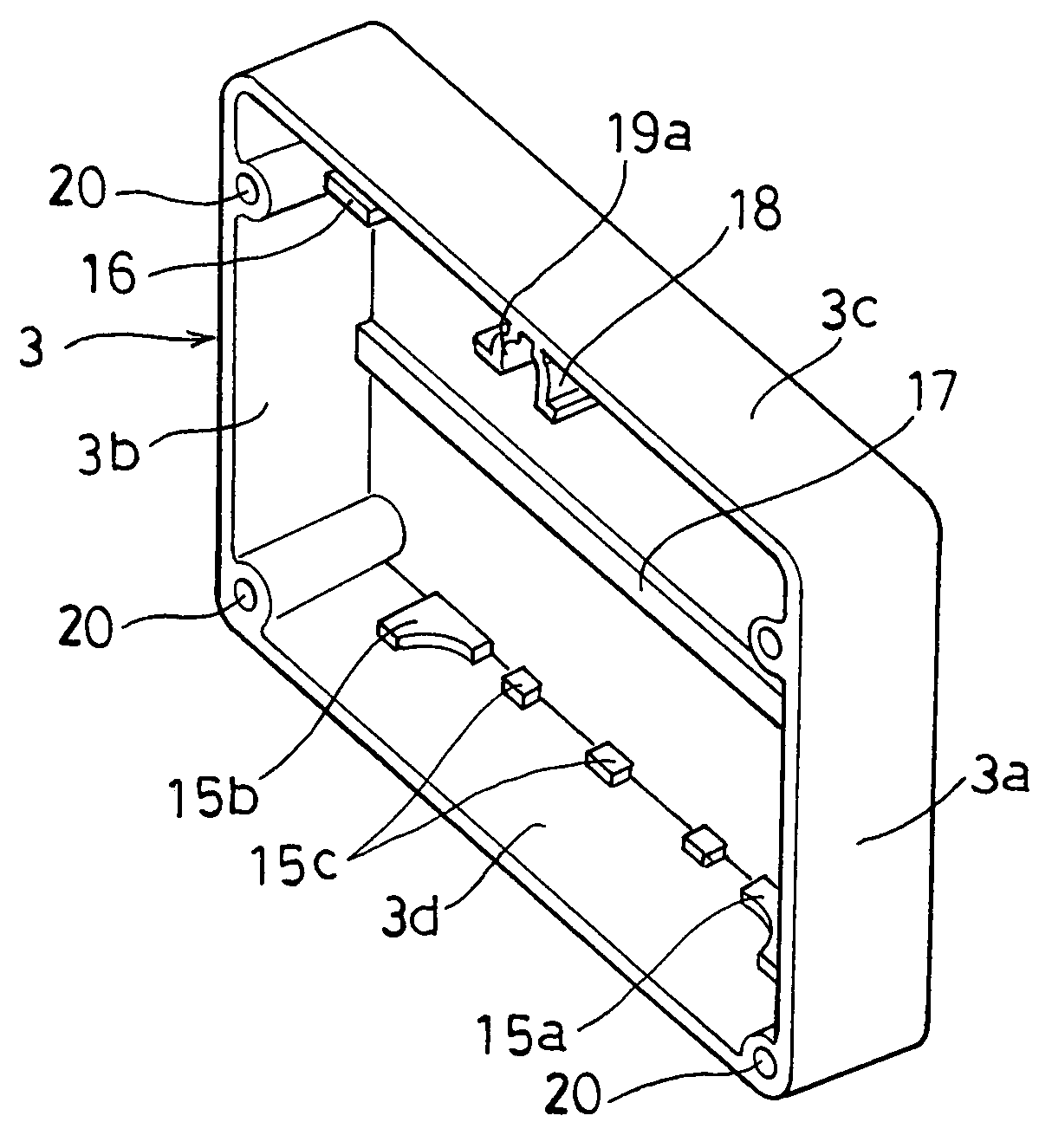
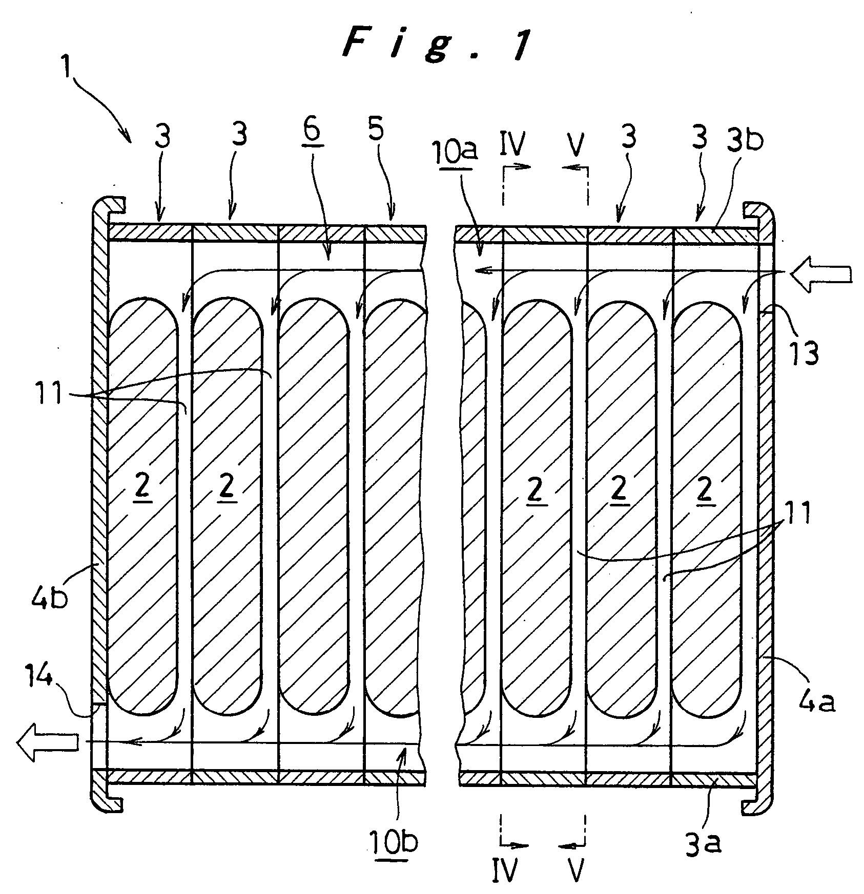
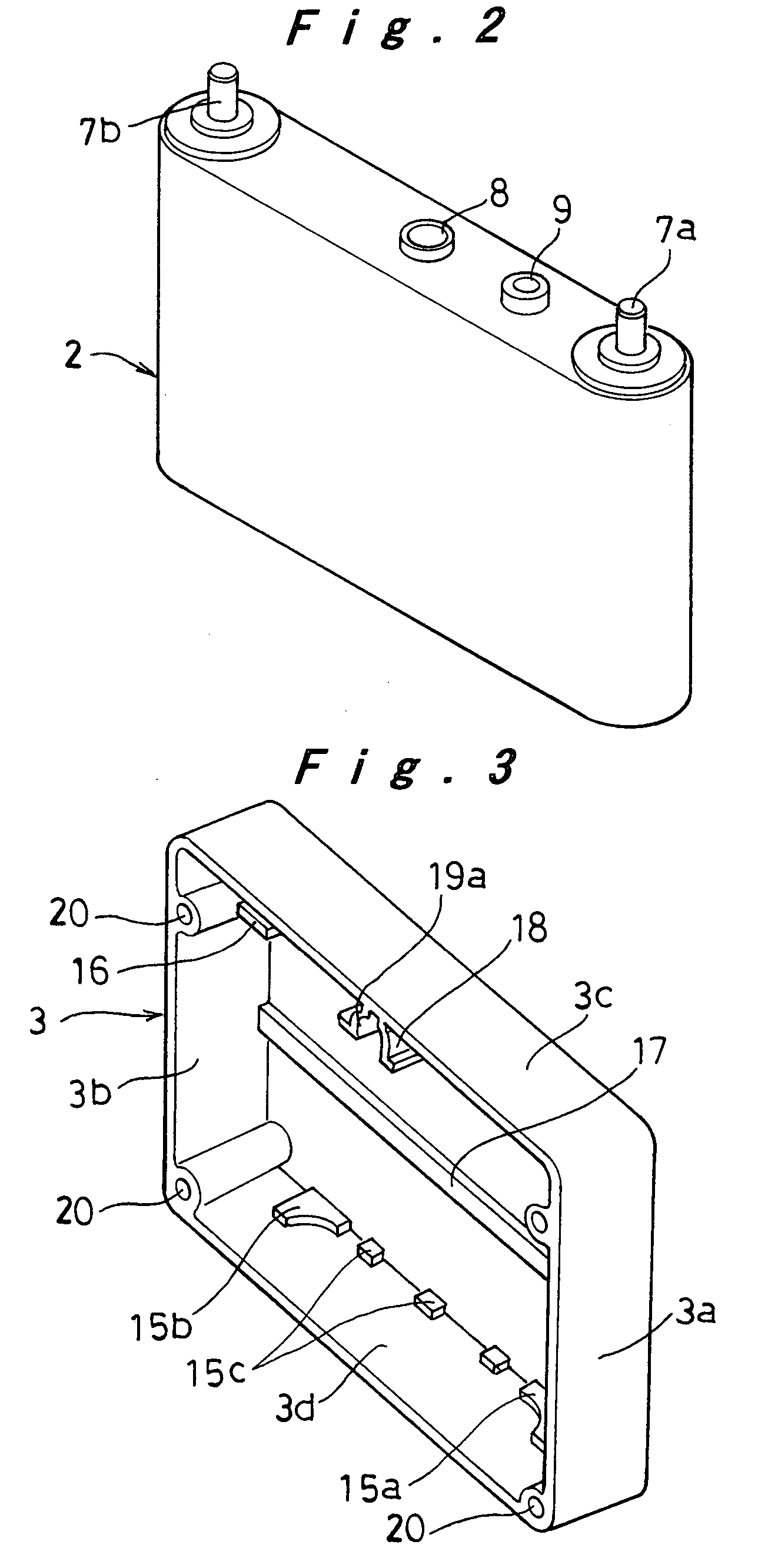
[0022] As shown in FIG. 1, in a battery pack 1, a battery 2 having an oval or oblong cross-sectional shape as shown in FIG. 2 is held by a holding frame 3 being a rectangular frame as shown in FIG. 3. A required number of the holding frames 3 are arranged in parallel. End plates 4a and 4b are provided at both ends of the thus arranged holding frames 3. The end plates 4a and 4b are fastened so that the end plates 4a and 4b and the holding frames 3 holding the batteries 2 are jointed together as a unit, thereby the battery pack 1 is formed. In the battery pack 1 thus formed, an outer case 5 for forming a cooling space 6 that surrounds each battery 2 is formed by the end plates 4a and 4b arranged at both ends and the plurality of holding frames 3 provided between the end plates 4a and 4b.

[0023] On the upper surface of the battery 2, positive and...


PUM


Abstract

A battery pack includes a plurality of batteries (2) and a plurality of holding frames (3) each of which is capable of accommodating and holding a corresponding one of the batteries (2) with spaces (10a, 10b) provided therein and which are opened on both side faces opposed to each other to form openings. When the holding frames (3) respectively accommodating and holding the batteries (2) are arranged with their openings aligned; end plates (4a, 4b) are arranged at both ends of the holding frames (3); and the end plates (4a, 4b) and the holding frames (3) are jointed as a unit so as to form an outer case (5) that forms a cooling space (6) surrounding each battery (2), a gas-discharge passage portion (18) is provided in each holding frame (3), which seals and covers a space surrounding a gas-discharge port (8) provided in the battery (2) and has connection ports (19a, 19b) opened on both side faces of the holding frame (3).

Description

TECHNICAL FIELD [0001] The present invention relates to a battery pack. More particularly, the present invention relates to a battery pack in which a plurality of batteries are arranged in parallel in an outer case and a cooling space is formed for cooling the batteries within the outer case. BACKGROUND ART [0002] In recent years, expectation for electric vehicles or hybrid electric vehicles has increased because of the global environmental problems. For rechargeable batteries as the power supply of those vehicles, both reduction in the size and weight and increase of the capacity and output are demanded. Thus, a battery pack in which a plurality of batteries formed by cells are connected in series is used as the power supply. Moreover, a battery pack in which, in order to cool respective batteries, the batteries are arranged in parallel in an outer case and a cool air from the vehicle interior is introduced by a fan into the outer case is known from Japanese Patent Laid-Open Public...

Claims


Application Information

Patent Timeline
IPC IPC(8): H01M6/42H01M10/60H01M10/613H01M10/625H01M10/647H01M10/6557H01M10/6563H01M50/213H01M50/291H01M50/503H01M50/51H01M50/517
CPCH01M2/0245H01M2/10H01M2/105H01M2/12H01M10/5067H01M2/26H01M6/42H01M10/5004H01M10/5016H01M2/202H01M10/625H01M10/6563H01M10/613Y02E60/10H01M50/258H01M50/213H01M50/30H01M50/51H01M50/517H01M50/503H01M50/291
Inventor IWAMURA, AKIRAKIMURA, KENJI
Owner PANASONIC CORP
Why Eureka
Try Eureka