Connector header grommet for an implantable medical device

a technology of connecting grommets and medical devices, which is applied in electrotherapy, therapy, etc., can solve the problems of fluid intrusion prevention, difficult removal of cured silicone rubber adhesives, and difficulty in fitting very small rigid or flexible plugs into the further header aperture, so as to reduce the amount of punching and coring of the penetrable socket, facilitate the insertion of the tool through the grommet slit, and limit the advancement of the setcrew

Active Publication Date: 2005-06-16
MEDTRONIC INC
View PDF22 Cites 40 Cited by
  • Summary
  • Abstract
  • Description
  • Claims
  • Application Information

AI Technical Summary

Benefits of technology

[0040] In accordance with one aspect of the present invention, a ring-shaped retainer having a central bore that a tool, e.g., a hex wrench, can be passed through is disposed against an annular portion of the outer end wall and is affixed to an annular portion of the header body surrounding the annular portion of the outer end wall. Advantageously, substantially the full length of the pre-formed slit is disposed within the header grommet aperture below the ring-shaped retainer so that the contact between the grommet sidewall and the grommet aperture sidewall tends to provide a uniform pressure to the pre-formed slit between the outer and inner end walls of the disc-shaped, penetrable grommet.
[0050] During implantation, a setscrew tool is inserted through the grommet slit into the setscrew socket and rotated to advance the setscrew threads along the threads of the threaded bore in the tightening direction until the setscrew working end engages the lead connector element. The application of the enlarged diameter setscrew socket end against the inner end wall of the penetrable grommet stabilizes the penetrable grommet from being unduly pressed inward by setscrew tool and minimizes punch out and coring of the penetrable socket.

Problems solved by technology

Sealing or closing the further header aperture from fluid intrusion is a somewhat more difficult problem to solve, and various methods have been developed and implemented over the years.
The cured silicone rubber adhesive is also difficult to remove after chronic implantation to be able to replace the electrical medical lead or the IPG or monitor.
Fitting very small rigid or flexible plugs into the further header aperture is difficult, and they can be dislodged and lost during the procedure.
In addition, due to their small size, both are quite difficult to handle directly by hand, which is quite undesirable during surgery.
It is also not possible to immediately confirm that a fluid tight seal has been achieved.
Again, the combined plug and setscrew can be mishandled, and it is also not always possible to confirm that a fluid tight seal has been achieved.
Moreover, epoxy connector bodies remain relatively rigid and dimensionally stable during chronic implantation, so that separation and loss of adhesion does not readily occur.
The use of the penetrable grommet simplified manufacturing and solved many of the problems associated with use of separate caps or plugs that the physician had to use to fill the further header aperture as described above, but other problems were observed over time.
The in situ molding process for forming the connector header body does not lend itself to mass production, since it does not involve use of interchangeable parts, and because the steps have to be done carefully and slowly.
Bubbles, voids, surface blemishes and other defects can occur requiring rework or scrapping of the product.
These drawbacks became more apparent and difficult to resolve as connector headers were reduced in size and incorporated increasing numbers of connector blocks and feedthroughs.
However, problems have been observed as the size of the pre-formed penetrable grommets and the corresponding header grommet apertures have been reduced.
However, the possibility of coring the pre-formed penetrable grommet by the hex wrench inserted through the pre-formed slit increases as the diameter of the pre-formed penetrable grommet is decreased.
Even the proper insertion of the hex wrench through the pre-formed slit can cause coring of the silicone rubber and deposition of the cored silicone rubber within the setscrew socket.
The cored slit cannot properly seal, and the silicone rubber lodged within the setscrew socket can block insertion of the hex wrench into the socket.
Whether or not such an approach has merit, fabrication of such a pre-formed grommet with a rigid, ring-shaped, stiffener element may be difficult.
Even the proper insertion of the hex wrench through the pre-formed slit can also cause loss of adhesion of the grommet to the grommet aperture wall surrounding it unless the penetrable grommet is designed to yield and distribute stresses away from the grommet aperture wall as the hex wrench is advanced through the slit.
The silicone rubber of the pre-formed penetrable grommet does not inherently adhere well with the material, particularly, TECOTHANE® urethane, of the pre-formed connector header body.
Forming one or more retention ridge in the header grommet aperture sidewall to engage the sidewall of the silicone rubber grommet as shown in the above-referenced '928 patent, for example, is difficult if not impossible due to the injection molding of the pre-formed connector body from TECOTHANE® urethane.
The application of minute amounts of adhesive complicates assembly, and non-destructive testing of the resulting adhesion strength is difficult to accomplish.
Other problems have been observed with the use of silicone rubber to form such penetrable grommets and urethanes to form connector header bodies.
The epoxy or urethane connector header body and the silicone rubber grommet are both translucent and substantially colorless or of a slight color such that there is little visible contrast therebetween, rendering it difficult to visually distinguish a penetrable grommet from the surrounding connector header body and to locate the pre-formed slit.
This could cause damage to the penetrable grommet compromising the ability of the pre-formed slit to reseal.
After prolonged storage or chronic implantation, it becomes more difficult to insert a hex wrench through the pre-formed slit without coring or dislodging the penetrable grommet from the header grommet aperture.
It has also been found that connector header bodies formed of TECOTHANE® urethane exhibit cold flow or creep at points or surfaces where pressure is applied chronically.
It has been observed that adhesion is lost between the grommet and header grommet aperture sidewalls when the grommet exerts pressure over time against the header grommet aperture sidewall causing expansion of the header grommet aperture diameter.
In addition, the TECOTHANE® urethane connector header body becomes slightly less rigid and dimensionally stable during chronic implantation in body fluids thereby aggravating the cold flow problem and negatively affecting adhesion with the silicone rubber grommet over time that can lead to spontaneous dislodgement of the grommet.
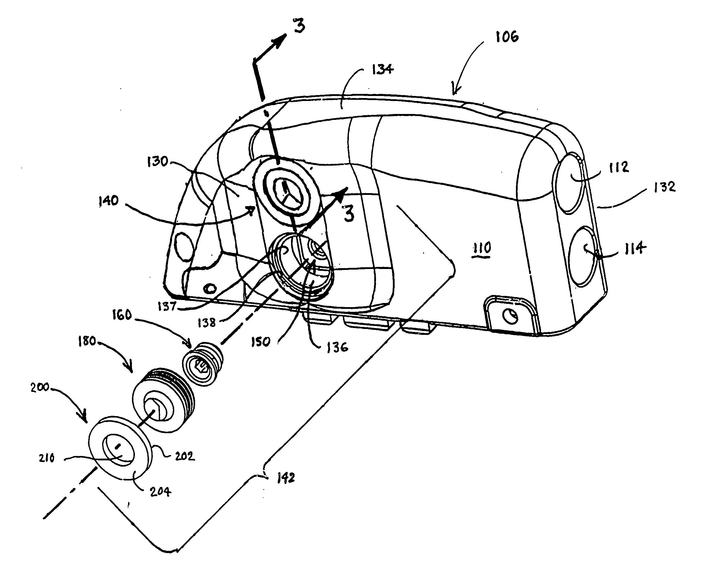
Further problems arise as the setscrews and connector blocks are miniaturized.
As noted above, it can be difficult to locate such a shallow setscrew socket with the hex wrench, and adhesive and / or dislodged silicone rubber can block the shallow setscrew socket.
One problem that has occurred due to the tolerances and the involves the inappropriate positioning during manufacture or spontaneous movement of the setscrew within the threaded bore due simply to handling and shipment that cannot be observed when the setscrew is covered by the penetrable grommet.
The physician inserting the connector lead element into the connector block bore may incorrectly assume that it is properly inserted and tighten down the setscrew without making contact, resulting in a connection failure that may or may not be detected at the time of implantation.
Therefore, despite the improvements that have been made in connector headers over the years, problems remain to be solved in the design and fabrication of connector headers of the type employing penetrable grommets disposed in header grommet apertures overlying fasteners, e.g., setscrews, employed to attach lead connector elements with connector blocks of the connector header.

Method used


Image

  • Connector header grommet for an implantable medical device
  • Connector header grommet for an implantable medical device
  • Connector header grommet for an implantable medical device

Examples


Embodiment Construction

[0072] In the following detailed description, references are made to illustrative embodiments of methods and apparatus for carrying out the invention. It is understood that other embodiments can be utilized without departing from the scope of the invention. Methods and apparatus are described for attaching lead connector elements of electrical medical leads received within connector bores of connector headers attached to hermetically sealed enclosures of IPGs or monitors of any of the types known in the art.

[0073] For example, a pacemaker IPG 100 is illustrated in FIG. 1 adapted to be attached to a bipolar atrial endocardial pacing lead 116 and attached to a bipolar ventricular endocardial pacing leads 118 extending in a transvenous pathway from the subcutaneous site of implantation of the IPG 100 into the right atrium and right ventricle of a patient's heart 16, respectively. The bipolar atrial endocardial pacing lead 116 comprises an elongated lead body enclosing a pair of electr...


PUM


Abstract

Improvements in connector headers of implantable medical devices (IMDS) for making electrical and mechanical connections with a connector element of a proximal connector assembly of an electrical medical lead and components thereof are disclosed. A connector block disposed within a header body of the connector header has a threaded bore aligned with a header grommet aperture and a connector block bore aligned with a header connector bore. A penetrable grommet is disposed within the header grommet aperture, and a setscrew is threaded into the threaded bore having a setscrew socket disposed to be engaged by the tool inserted through the penetrable grommet within the header grommet aperture to enable rotation of the setscrew within the threaded bore to tighten the setscrew against or to loosen the setscrew from a lead connector element received in the header connector bore.

Description

REFERENCE TO RELATED APPLICATIONS [0001] Reference is hereby made to U.S. patent application Ser. No. 10 / 199,601 filed Jul. 19, 2002, which is a continuation in part of U.S. patent application Ser. No. 09 / 767,796 filed Jan. 23, 2000, which is a continuation of U.S. patent application Ser. No. 09 / 417,157 filed Oct. 12, 1999 now abandoned, which is a continuation of U.S. patent application Ser. No. 09 / 159,119 filed Sep. 28, 1998, which is a divisional of U.S. patent application Ser. No. 08 / 904,636 filed Aug. 1, 1997, now abandoned all of which are herein incorporated by reference. [0002] Reference is also made to commonly assigned U.S. patent application Ser. No. (P-11597) filed on even date herewith for CONNECTOR HEADER SETSCREW FOR AN IMPLANTABLE MEDICAL DEVICE in the names of Jennifer J. Zhao et al., and commonly assigned U.S. patent application Ser. No. (P-7670.07) filed on even date herewith for CONNECTOR HEADER FOR AN IMPLANTABLE MEDICAL DEVICE in the names of Kevin K. Tidemand ...

Claims


Application Information

Patent Timeline
Patent Type & Authority Applications(United States)
IPC IPC(8): A61N1/375
CPCA61N1/3752
Inventor RIES, ANDREW J.TIDEMAND, KEVIN K.ZHAO, JENNIFER J.RICE, DAVID C.JIN, HUI
Owner MEDTRONIC INC
Why Eureka
Try Eureka