Golf club head and manufacturing method of the same

a manufacturing method and golf club technology, applied in the field of golf club heads, can solve the problems of reducing adhesive strength, affecting the appearance of the head, and the fitting of both the members, so as to inhibit the defect of molding, improve the flow property, and improve the effect of the molding

Active Publication Date: 2007-10-16
SUMITOMO RUBBER IND LTD
View PDF20 Cites 48 Cited by
  • Summary
  • Abstract
  • Description
  • Claims
  • Application Information

AI Technical Summary

Benefits of technology

[0008]The present invention is made by taking the actual condition mentioned above into consideration, and a main object of the present invention is to provide a golf club head which is possible to improve a flow property of the prepreg which is in contact with a bladder, and it is possible to inhibit a defect in molding from being generated by uniformly applying a pressure to the laminated body by extension.
[0009]In accordance with the invention on the basis of the first or sixth aspect, the laminated body of the prepreg constituting the resin member of the combined head is structured by a plurality of prepregs having the different resin percentage contents, and the prepreg having the largest resin percentage content is used in the innermost layer closest to the hollow portion. The prepreg having the larger resin percentage content has an improved flow property in a plasticized state in comparison with the prepreg having the smaller resin percentage content, and can obtain a great flow property (slip and deformation) on a surface at a time of being in contact with the bladder by extension. In other words, the surface can flexibly follow a shape of the bladder, and it is possible to uniformly transmit the pressure to the outside prepreg. Accordingly, it is possible to apply a uniform pressure to each of the portions of the laminated body, and it is possible to inhibit the defect in molding such as the crimple from being generated in the resin member.
[0010]Further, in accordance with the invention on the basis of the fifth aspect, the laminated body of the prepreg constituting the resin member of the combined head is structured by a plurality of prepregs having the different resin percentage contents, at least one layer of the prepreg having the smallest resin percentage content is used in an intermediate layer arranged between the innermost layer and the outermost layer, and the prepreg having the larger resin percentage content than that of the prepreg having the smallest resin percentage content is used in the innermost layer and the outermost layer. As a result, it is possible to improve the flow property at a time of being in contact with the cavity even in the outermost layer of the laminated body which is in contact with the cavity of the metal mold. Accordingly, in accordance with the invention, the innermost layer of the laminated body can flexibly follow the shape of the bladder, and the outermost layer can flexibly follow the shape of the cavity, whereby it is possible to further inhibit the defect in molding such as the crimple or the like from being generated in the resin member.

Problems solved by technology

However, in accordance with the adhesive bonding method, a gap or a step tends to be formed on the boundary of a junction between the head shell portion and the resin member, and an outer appearance and a showing of the head tend to be deteriorated.
Further, there is a risk that a fitting of both the members does not stabilize due to a dispersion in manufacturing the head shell portion and / or the resin member, and there is a risk that an adhesive strength is lowered, by extension.
However, the internal pressure molding method has the following disadvantage.
However, there is a case that a temporal shift is generated in each of portions in the contact between the bladder B and the laminated body P at a time of inflating the bladder B, whereby an uneven internal pressure is applied to the laminated body P. As a result, the laminated body P can not uniformly inflate to the outer side, and a defect in molding such as a crimple and a concavity and convexity is generated on a surface of the molded resin member.
Further, since not only the crimple and the concavity and convexity generate a problem in the outer appearance, but also the reinforced fiber in this part is folded, it is impossible to obtain a sufficient strength and the crimple and the concavity and convexity tend to generate a starting point of a damage.

Method used


Image

  • Golf club head and manufacturing method of the same
  • Golf club head and manufacturing method of the same
  • Golf club head and manufacturing method of the same

Examples


examples

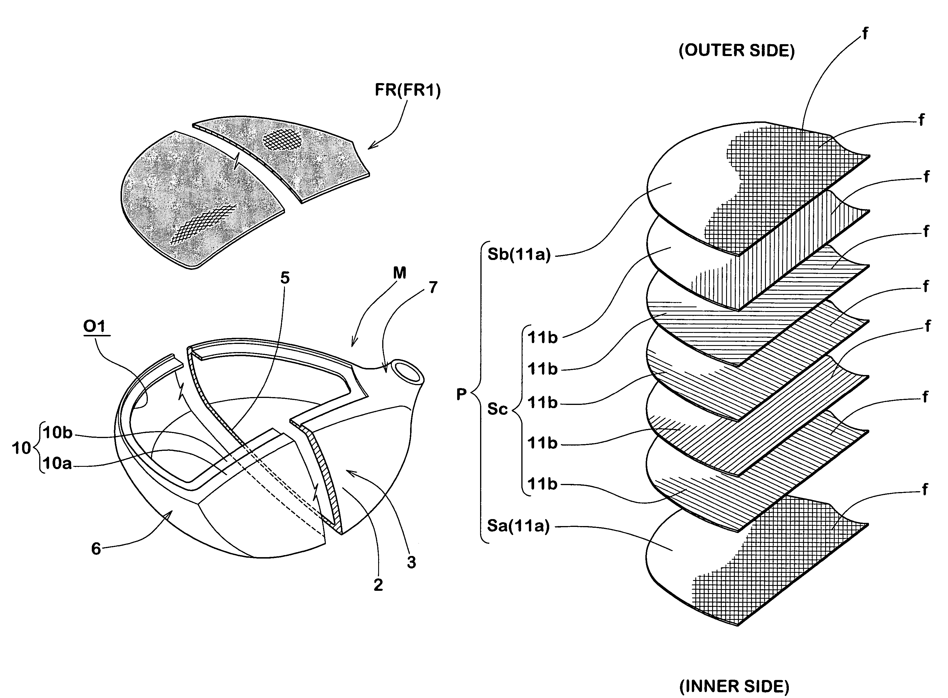
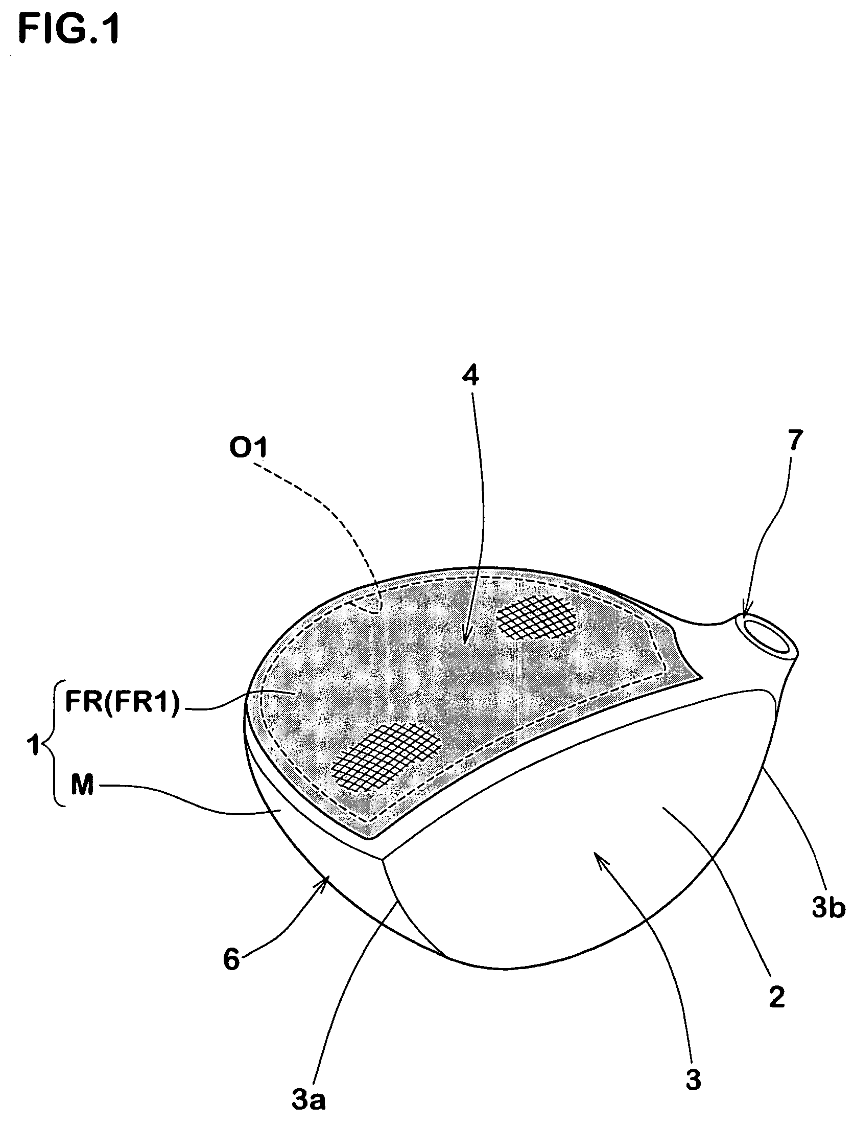
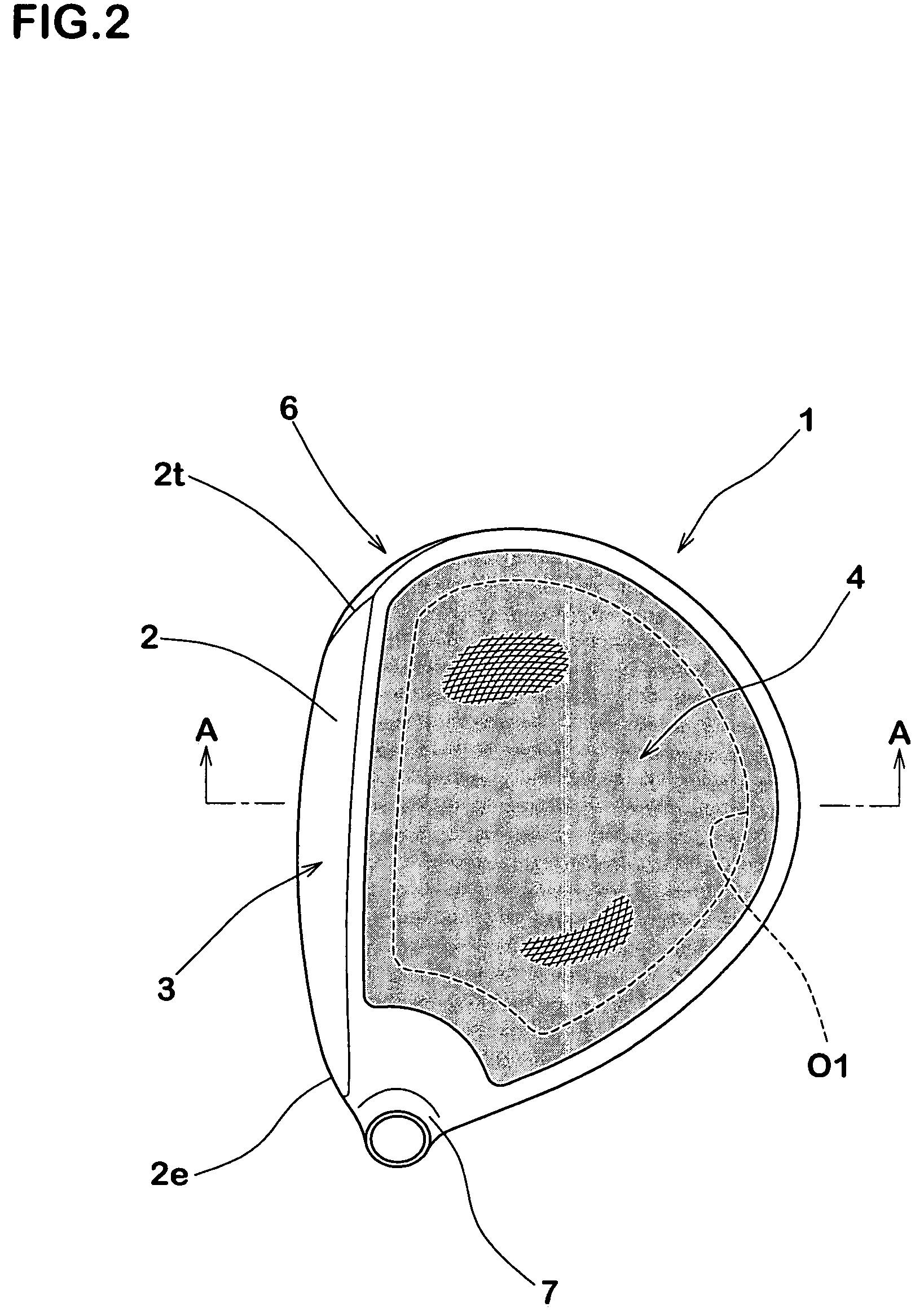
[0059]In order to confirm the effect of the present invention, a wood type driver head having a head volume of 420 cm3 is manufactured by way of trial on the basis of the specification in FIGS. 1 to 3 and Table 1. The ratio S1 / S mentioned above between the area S1 of the opening portion and the head area S is set to 0.8. The head shell portion and the resin member are formed in the shape shown in FIGS. 1 to 5. Further, the laminated body of the prepreg employs the prepregs shown by the order of reference symbols (a) to (g) from the outermost layer to the innermost layer, as shown in FIG. 13. A fiber of each of the prepregs, an angle of orientation and a direction of fiber are as illustrated. Further, each of the prepregs (CFRP) using the carbon fiber is constituted by a composite material of a carbon fiber having an elastic modulus in tension of 235 GPa and an epoxy resin. Further, in each of the prepregs, the resin percentage content is differentiated as shown in Table 1.

[0060]The ...


PUM

PropertyMeasurementUnit
elastic modulusaaaaaaaaaa

Abstract

The invention prevents a crimple from being generated in a resin member. The invention provides a golf club head (1) including a head shell portion (M) made of a metal material and having an opening portion (O1), and a resin member (FR) made of a fiber reinforced resin arranged in the opening portion (O1), and provided with a hollow portion in an inner portion. The resin member (FR) is constituted by a molded body formed by integrally molding a laminated body of plural layers of prepregs having a magnitude covering the opening portion (O1) and having different resin percentage contents in the head shell portion in accordance with an internal pressure molding method. Further, the prepreg having the largest resin percentage content is used in an innermost layer of the laminated body closest to the hollow portion.

Description

BACKGROUND OF THE INVENTION[0001]1. Field of the Invention[0002]The present invention relates to a golf club head structured by using a metal material and a fiber reinforced resin, and a manufacturing method of the same.[0003]2. Prior Art[0004]There have been proposed various golf club heads in which a fiber reinforced resin member is combined in a part of a metal material member which is main part of the golf club head (hereinafter, this may be sometimes called simply as “combined head”). A weight of the combined head can be reduced by using the parts made of a fiber reinforced resin having a small specific gravity, and there is an advantage that a freedom of designing a weight distribution of the head can be improved by allocating the reduced weight to a side portion of the head, for example, a toe or a heel, or allocating to a back face.[0005]Further, the combined head can be manufactured by adhering a resin member made of a fiber reinforced resin and previously molded in a prede...

Claims


Application Information

Patent Timeline
Patent Type & Authority Patents(United States)
IPC IPC(8): A63B53/04B29C45/14B29D22/00A63B102/32
CPCA63B53/0466A63B2209/02A63B2209/023A63B2053/0437A63B2053/0433A63B2053/0408A63B2209/026A63B53/0408A63B53/0433A63B53/0437
Inventor OYAMA, HITOSHI
Owner SUMITOMO RUBBER IND LTD
Why Eureka
Try Eureka