Refrigerator and ice maker apparatus

a technology of refrigerator and ice maker, which is applied in the field of refrigerators, can solve the problems that the known ice buckets do not permit easy access to bulk ice removal

Inactive Publication Date: 2005-06-23
GENERAL ELECTRIC CO
View PDF13 Cites 55 Cited by
  • Summary
  • Abstract
  • Description
  • Claims
  • Application Information

AI Technical Summary

Problems solved by technology

Known ice buckets do not permit easy access to bulk ice removal, due to interference with the inner door when the refrigerator is adjacent to a wall, especially for “built-in: style refrigerators.

Method used


Image

  • Refrigerator and ice maker apparatus
  • Refrigerator and ice maker apparatus
  • Refrigerator and ice maker apparatus

Examples


Embodiment Construction

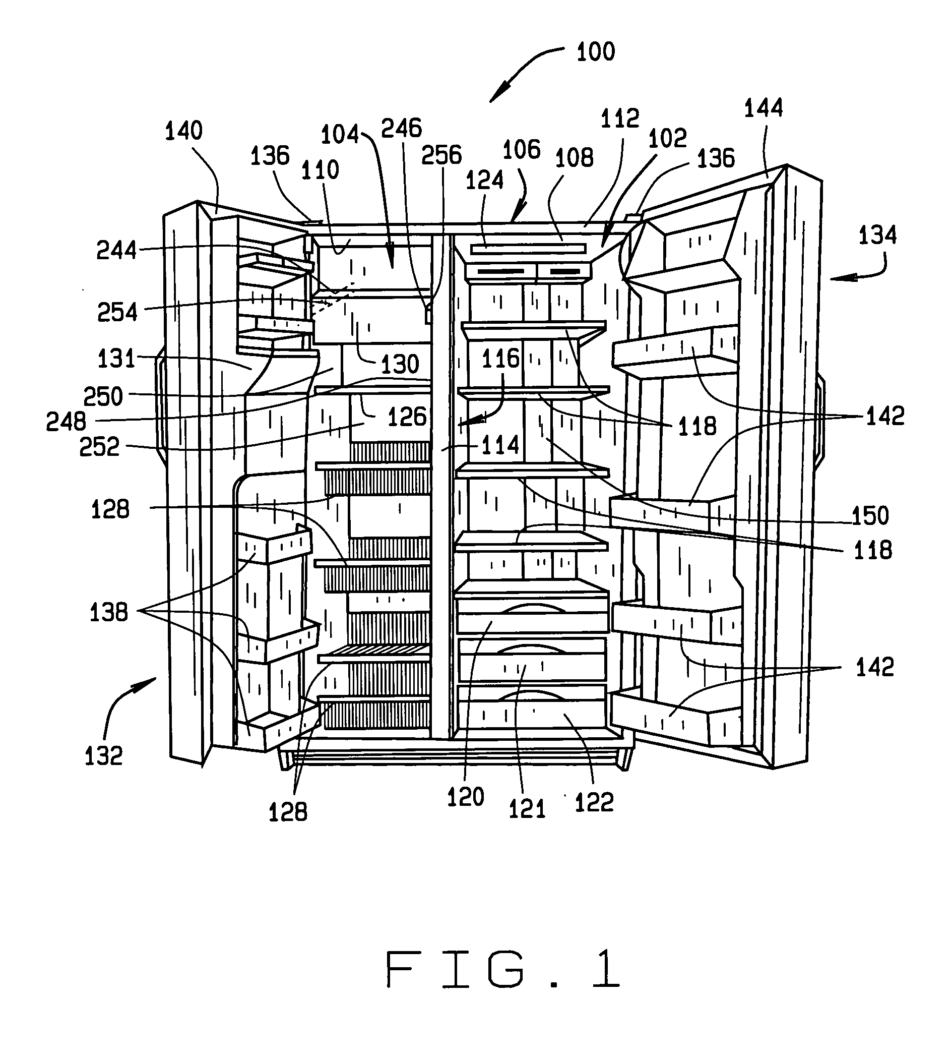
[0016]FIG. 1 illustrates an exemplary refrigeration appliance 100 in which the present invention may be practiced. In the embodiment described and illustrated herein, appliance 100 is a side-by-side refrigerator. It is recognized, however, that the benefits of the present invention are equally applicable to other types of refrigerators, freezers, and refrigeration appliances. Consequently, the description set forth herein is for illustrative purposes only and is not intended to limit the invention in any aspect.

[0017] Refrigerator 100 includes a fresh food storage compartment 102 and a freezer storage compartment 104 contained within an outer case 106 and inner liners 108 and 110. A space between case 106 and liners 108 and 110, and between liners 108 and 110, is filled with foamed-in-place insulation. Outer case 106 normally is formed by folding a sheet of a suitable material, such as pre-painted steel, into an inverted U-shape to form top and side walls of case. A bottom wall of ...


PUM


Abstract

An ice maker assembly includes, in an exemplary embodiment, an ice bucket that has a bottom wall, opposing side walls extending from the bottom wall, a front wall, and a back wall. The bottom wall, side walls, front wall, and back wall define an ice collection cavity. The ice bucket also includes a plurality of ribs extending from the bottom wall into the ice collection cavity, and a rotatable auger extending between the front and back walls.

Description

BACKGROUND OF THE INVENTION [0001] This invention relates generally to refrigerators, and more specifically, to an ice making system for a refrigerator. [0002] Some known refrigerators include a fresh food compartment and a freezer compartment. Such refrigerators also typically include a refrigeration circuit including a compressor, evaporator, and condenser connected in series. An evaporator fan is provided to blow air over the evaporator, and a condenser fan is provided to blow air over the condenser. In operation, when an upper temperature limit is reached in the freezer compartment, the compressor, evaporator fan, and condenser fan are energized. Once the temperature in the freezer compartment reaches a lower temperature limit, the compressor, evaporator fan, and condenser fan are de-energized. [0003] Some refrigerator freezers include an ice maker. The ice maker receives water for ice production from a water valve typically mounted to an exterior of a refrigerator case. A prima...

Claims


Application Information

Patent Timeline
Patent Type & Authority Applications(United States)
IPC IPC(8): F25C5/18
CPCF25C5/185F25D2400/06F25C2400/10F25C2400/04
Inventor SANNASI, ASHOK KUMARKING, SCOTT RUSSELLJANARDHANAM, RAMESHWHITE, LORINA JUNEARMSTRONG, JAMESRENZ, DANIEL STEPHENCOOPER, ANTHONY
Owner GENERAL ELECTRIC CO
Why Eureka
Try Eureka