Pulse systems and methods for detaching ice
a technology of pulsing systems and ice, applied in the direction of electric/magnetic/electromagnetic heating, lighting and heating apparatus, machine operation modes, etc., can solve the problems of reducing the efficiency and productivity of ice-maker, consuming significant heat flow, and wasting energy and tim
- Summary
- Abstract
- Description
- Claims
- Application Information
AI Technical Summary
Benefits of technology
Problems solved by technology
Method used
Image
Examples
example 2
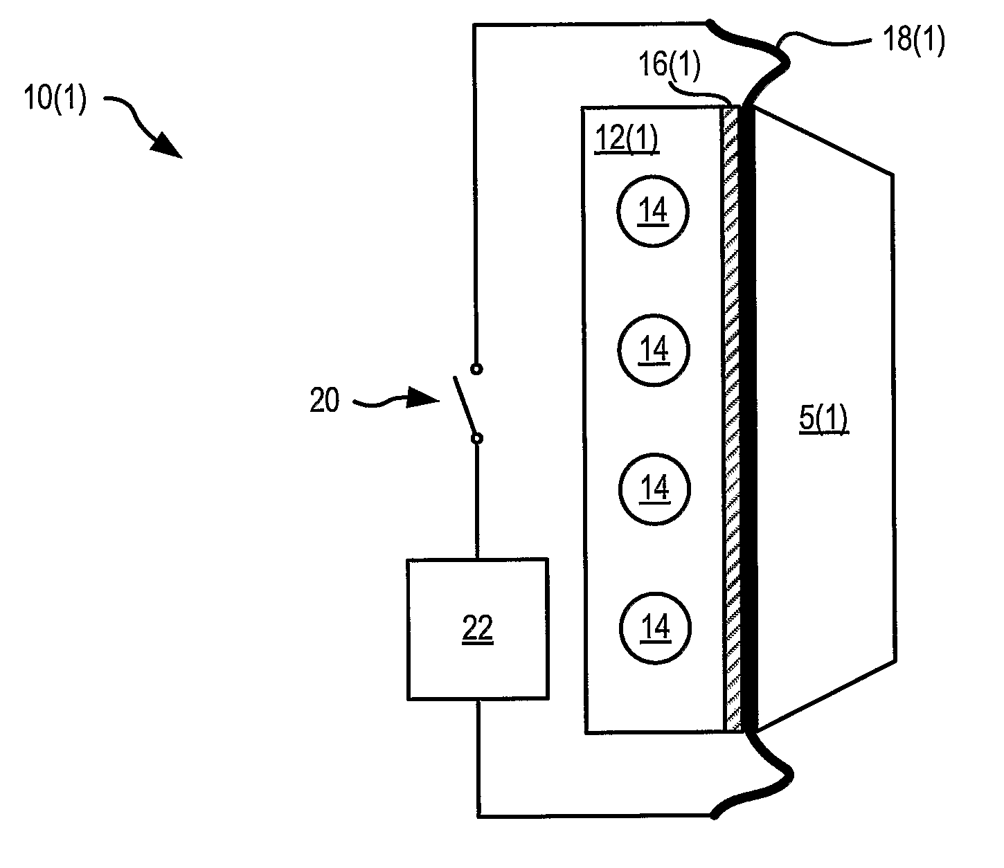
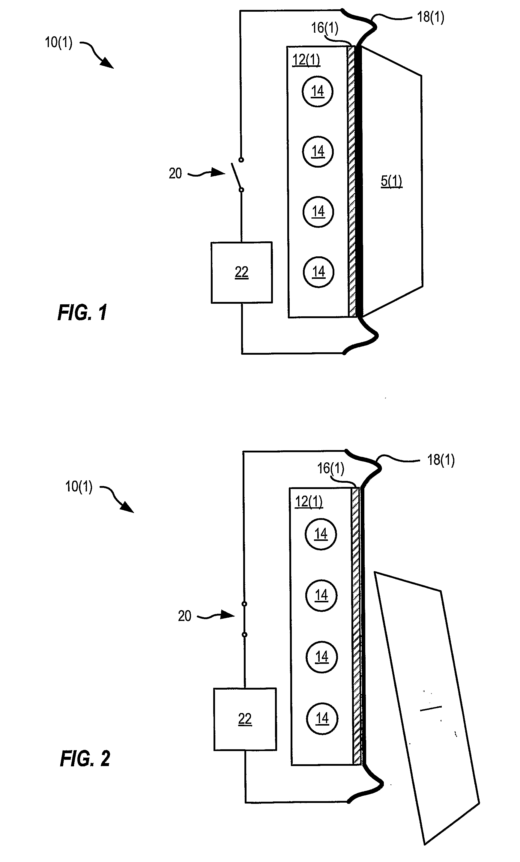
[0106]An example provides illustrative (non-limiting) specification and performance parameters of system 10(4) shown in FIG. 7 and FIG. 8. The following parameters are used as input for these calculations:
TABLE 3Constants and Variables used in Example 2ItemSymbolValueCold plate 12(1) temperature (below 0 C.)ΔT18 KAir gap widthdvariableAir density:ρd1.3kg / m3Air heat capacity:Cd103J / (kg · K)Air thermal conductivity:λd0.023W / (m · K)Foil 18(4) material:stainless steel foilFoil 18(4) thickness:dh0.1mmFoil 18(4) density:ρh7800kg / m3Foil 18(4) heat capacity:Ch450J / (kg · K)Foil 18(4) areaS0.645m2Power density applied to the heater-filmWvariableTime over which heating pulse is appliedtvariableIce 5(4) densityρi920kg / m3Ice 5(4) thermal conductivityλi2.2W / (m · K)Ice 5(4) heat capacityCi2.2 · 103J / (kg · K)Water densityρw1000kg / m3Latent heat of ice melting 5(1)qlatent3.33 · 105J / kgDesired thickness of melted ice layer:lm0.2mmDesired time before refreezing of thetr>2smelted layer
[0107]Heat diffusi...
example 3
[0135]FIG. 33 shows a cross section of one ice-making system 100(1) that utilizes both PETD and PEED. Ice-making system 100(1) has an ice-container 102(1) and a capillary 104(1) that may both be made, for example, of stainless steel. Container 102(1) and capillary 104(1) are filled with water that freezes to form a main ice portion 5(10) and a capillary ice portion 5(11). Container 102(1) may be shaped like a frustum.
[0136]Ice-making system 100(1) is powered by two power sources 108, 110 switched by two switches 112, 114, respectively. When ice is harvested from ice-making system 100(1), switch 114 first closes, supplying a first heating pulse to ice container 102(1), then switch 112 closes, supplying a second heating pulse to capillary 104(1). The first heating pulse has sufficient energy to melt at least an interfacial ice layer between container 102(1) and ice portion 5(10); the second heating pulse has sufficient energy to evaporate part or all of capillary ice portion 5(11). Pr...
example 4
[0144]FIG. 37A schematically shows a pulse electro-evaporative deicing system 130. System 130 includes a substrate 132 and a heating element 134, and is shown with ice 5(16) that forms an ice-object interface 136 at heating element 134. Heating element 134 has pores 138 that fill with ice 5(16). FIG. 37B shows pulse deicing system 130 after a heating pulse has been applied to heating element 134. Pressure from water vapor created at ice-object interface 136 of FIG. 37A, and in particular from water evaporated within pores 138, creates a space 140 between heating element 134 and ice 5(16).
[0145]A pulse deicing system according to the description of system 130 was built and tested. A porous stainless steel foil 0.32 mm thick was sintered of 53 μm to 75 μm particles; the foil had pores of about 10 μm. Water was placed on the foil and then frozen at T=−10° C., with part of the water penetrating and freezing in the pores of the foil. A 20 ms pulse of heating density 1.7×10⁷ W / m2 was appl...
PUM
 Abstract
Description
Claims
Application Information
 - R&D
- Intellectual Property
- Life Sciences
- Materials
- Tech Scout
- Unparalleled Data Quality
- Higher Quality Content
- 60% Fewer Hallucinations
Browse by: Latest US Patents, China's latest patents, Technical Efficacy Thesaurus, Application Domain, Technology Topic, Popular Technical Reports.
© 2025 PatSnap. All rights reserved.Legal|Privacy policy|Modern Slavery Act Transparency Statement|Sitemap|About US| Contact US: help@patsnap.com


