Single station tire curing method and apparatus

Inactive Publication Date: 2005-06-23
SIEVERDING MARK ANTHONY +2
View PDF12 Cites 45 Cited by
  • Summary
  • Abstract
  • Description
  • Claims
  • Application Information

AI Technical Summary

Benefits of technology

[0025]“Chafer” refers to reinforcing material (rubber alone, or fabric and rubber) around the bead in the rim flange area to prevent chafing of the tire by the rim parts.

Problems solved by technology

The tire curing process, however, may take upwards of four to twenty minutes for a passenger or light truck tire, depending on the tire size, more time, of course, for the larger tires such as earthmover, farm, truck and aviation tires.
It has come to the inventors' attention that such systems require large volumes of production runs, massive amounts of inventory of finished product and the associated cost of shipping and handling.

Method used


Image

  • Single station tire curing method and apparatus
  • Single station tire curing method and apparatus
  • Single station tire curing method and apparatus

Examples


Embodiment Construction

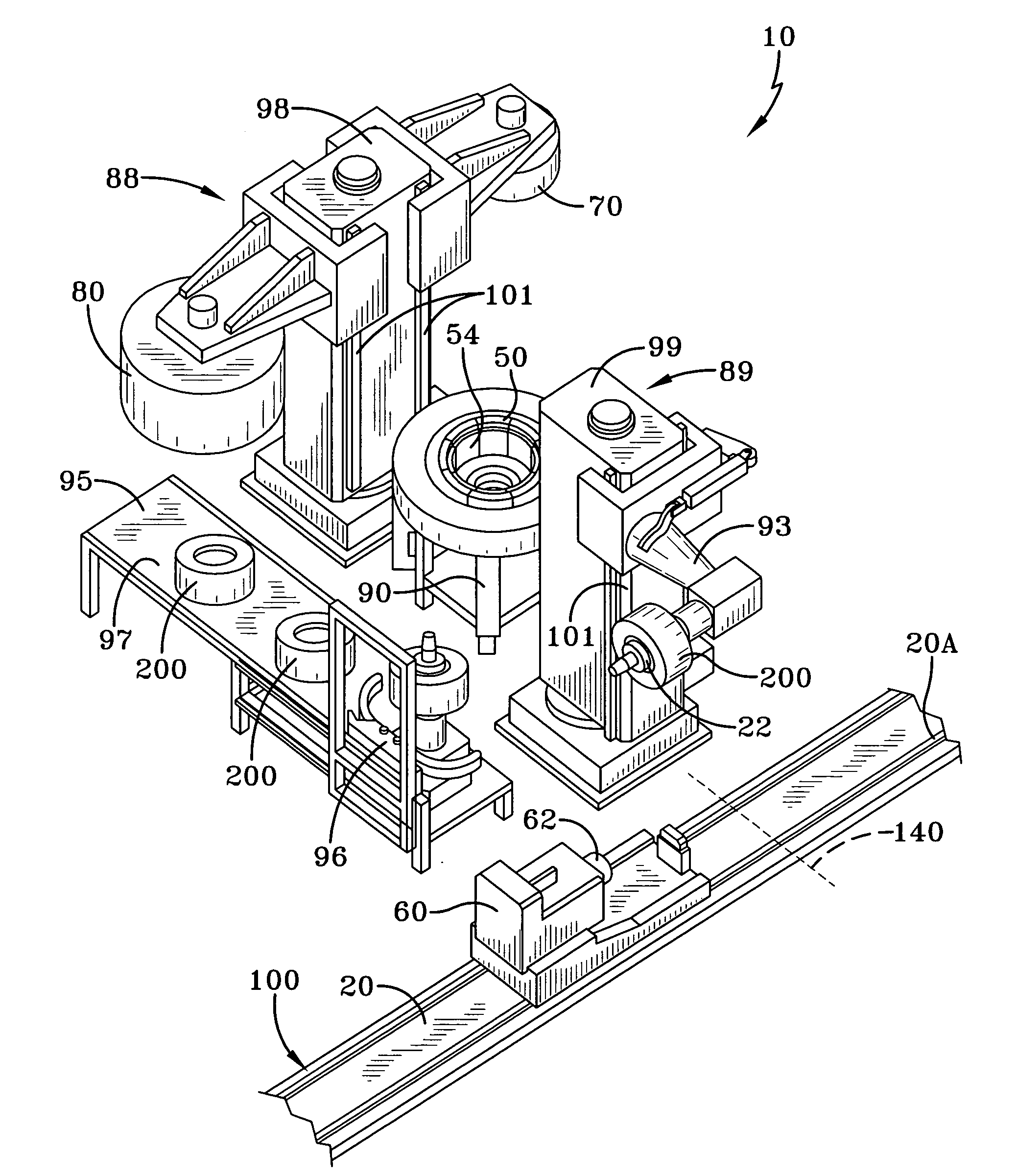
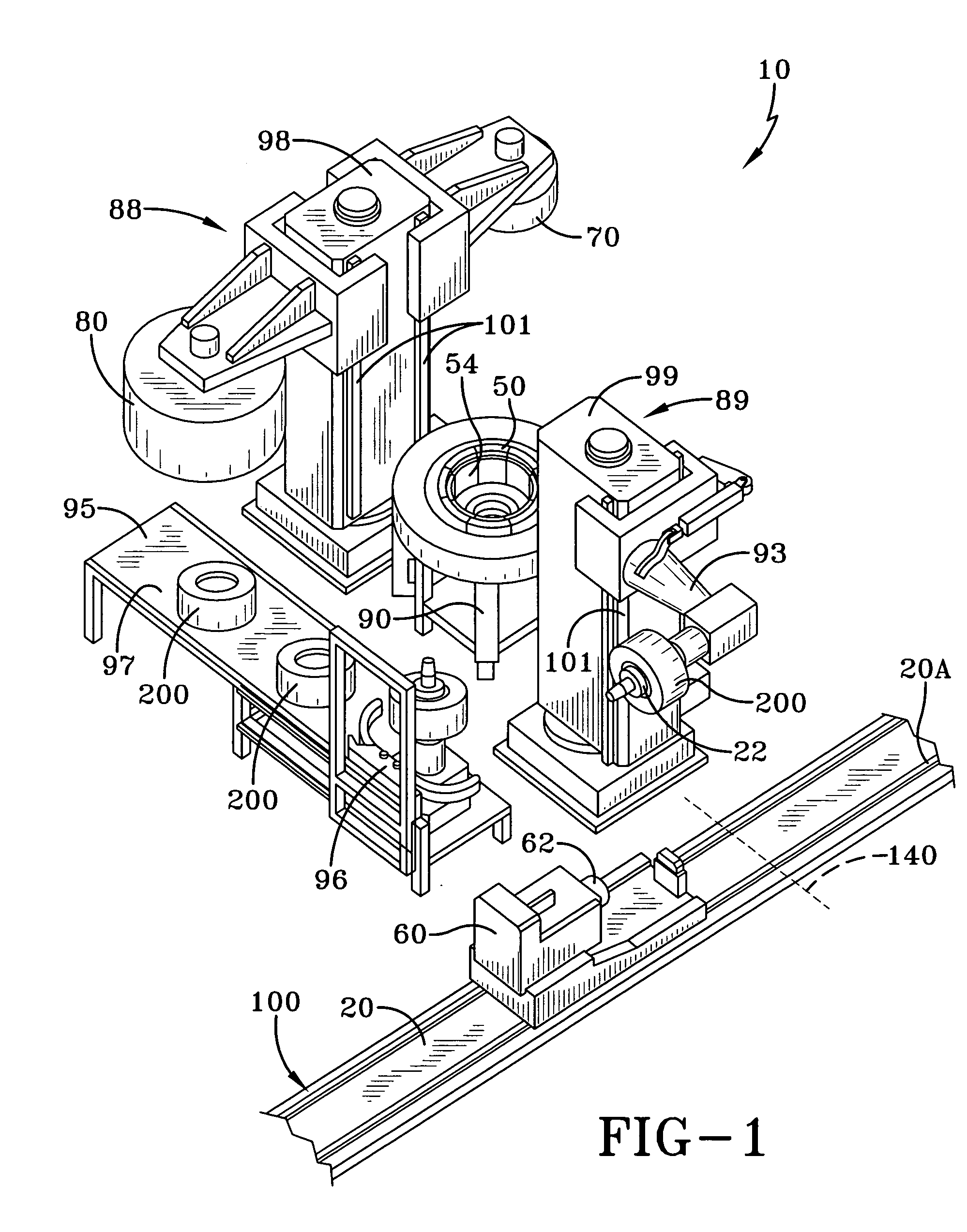
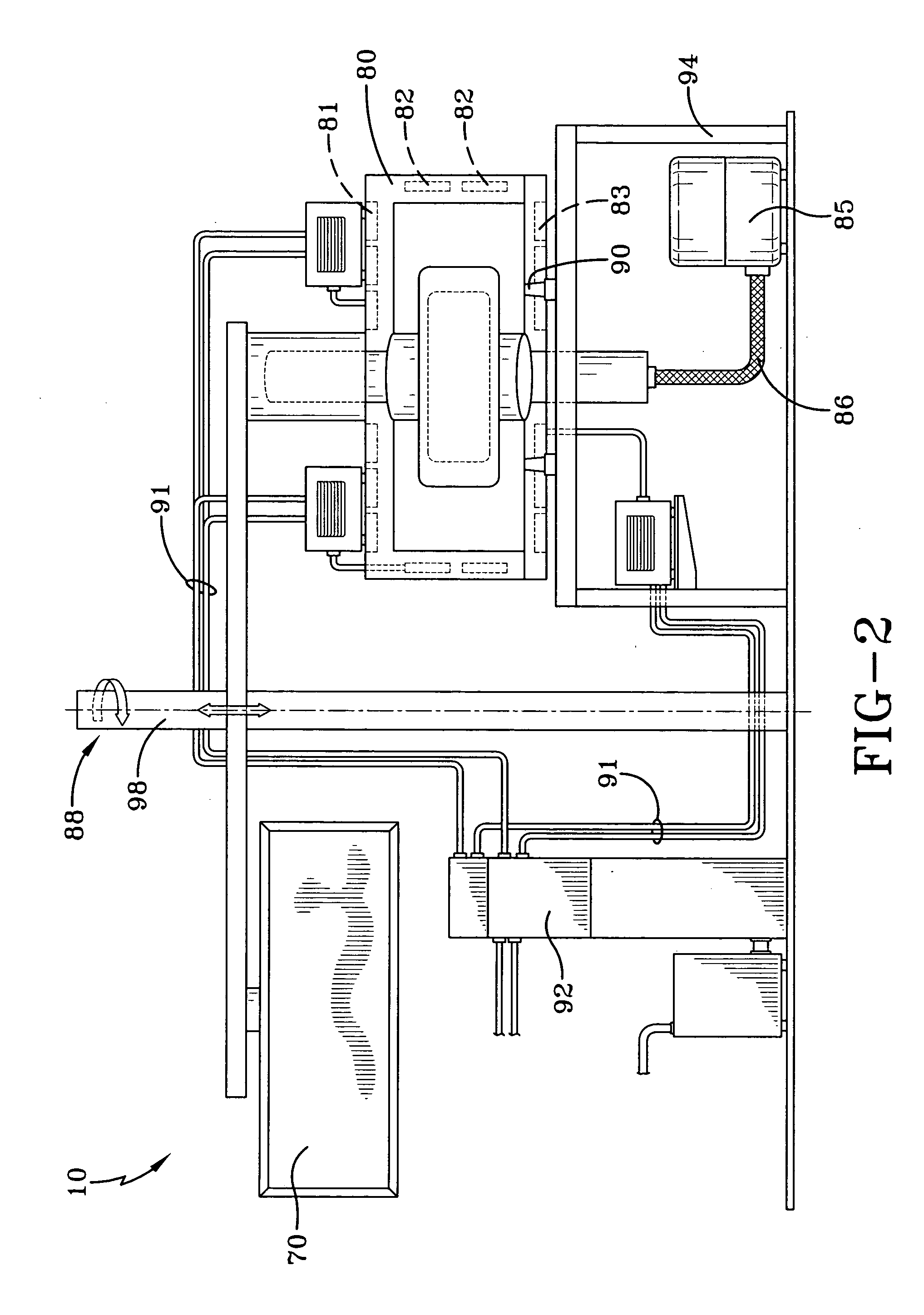
[0054] With reference to FIGS. 1 and 2, views of an automated tire manufacturing curing module 10 according to the present invention are illustrated. This system or module 10 provides for the complete vulcanization of pneumatic tires at one tire curing station using only one mold 50 for a particular tire size or style. This curing module 10 is preferably an integral part of a tire building module 100 which forms the tire carcass subassembly 4 and the tire belt tread subassembly 3. As shown in FIG. 7, these two subassemblies 3, 4 after being formed hot and assembled on a detachable elevated temperature building drum core 22 are shown inserted while on the building drum into a tire curing mold 50 immediately after their assembly is completed. When at the tire curing station, the mold 50 will then be closed and heated at a mold curing module 10 which permits the tires 200 to be cured or otherwise vulcanized and removed from the mold 50 and the building drum core 22.

[0055] In a related...


PUM

PropertyMeasurementUnit
Temperatureaaaaaaaaaa
Poweraaaaaaaaaa
Sizeaaaaaaaaaa

Abstract

An automated tire manufacturing curing module 10 according to the present invention is illustrated. This system or module 10 provides for the complete vulcanization of pneumatic tires at one tire curing module 10 using only one mold 50 for a particular tire size or style. This curing module 10 is preferably an integral part of a tire building module which forms the tire carcass subassembly 4 and the tire belt tread subassembly 3. These two subassemblies 3, 4 after being formed hot and assembled on a detachable elevated temperature building drum core 22 are shown inserted while on the building drum core 22 into a tire curing mold 50 immediately after their assembly is completed. When at the tire curing station, the mold 50 will then be closed and heated at a mold curing module 10 which permits the tires 200 to be cured or otherwise vulcanized and removed from the mold 50 and the building drum core 22. The curing module preferably has a curing dome 80 having one or more induction heating coils 81, 82, 83.

Description

CROSS-REFERENCE TO RELATED APPLICATIONS [0001] This application relates to the following U.S. patent applications entitled: “A Method and Apparatus for forming an Annular Elastomeric Tire Component”, U.S. Ser. No. 10 / 291,279, filed on Nov. 8, 2002; “An Improved Method and Apparatus for Manufacturing Carcass Plies For a Tire”, U.S. Ser. No. 10 / 365,374, filed on Feb. 11, 2003; “Radially Expansible Tire Assembly Drum and Method For Forming Tires”, Ser. No. 10 / 388,773, filed Mar. 14, 2003; “Method and Apparatus For Tread Belt Assemblies”, Docket No. DN2003-078, filed on May 20, 2003; and “A Method For Curing Tires and a Self-Locking Tire Mold”, U.S. Ser. No. 10 / 417,849, filed Apr. 17, 2003; “Method for Manufacturing Tires on a Flexible Manufacturing System, U.S. Ser. No. 10 / 449,468, filed May 30, 2003, “Tire Manufacturing Module and Method of Manufacturing Tires”, U.S. Ser. No. ______ (Attorney Docket Number DN2003-201) filed Dec. 11, 2003.FIELD OF THE INVENTION [0002] This invention re...

Claims


Application Information

Patent Timeline
IPC IPC(8): B29C35/02B29C35/08B29C33/02B29C35/12B29D30/06B29D30/10B29D30/20B29L30/00
CPCB29C2035/0811B29D30/0601B29D2030/105B29D30/10B29D30/0661B29D30/20B29C35/02B29C35/12
Inventor SIEVERDING, MARK ANTHONYSATRAPE, JAMES VINCENTGIRARD, JEAN-CLAUDE
Owner SIEVERDING MARK ANTHONY
Why Eureka
Try Eureka