Modular rackmount chiller

a rackmount chiller and module technology, applied in the field of electronic assemblies, can solve the problems of limited cooling capacity, difficult access to the rackmount multi-board chassis or sub-assembly, and the general requirement of electrical power for more powerful electronics, so as to achieve the effect of convenient access or removal

Inactive Publication Date: 2005-06-23
AMPHENOL CORP
View PDF22 Cites 70 Cited by
  • Summary
  • Abstract
  • Description
  • Claims
  • Application Information

AI Technical Summary

Benefits of technology

[0017] In another embodiment, the chiller has components that can be easily accessed or removed when the chiller is mounted in a rack. The preferred embodiment has blind-mate electrical connections to a fan assembly and a power supply so that these components can be inserted into the assembly without removing the entire chiller from the rack. In a most preferred embodiment, a pump on the chiller includes a magnetically c

Problems solved by technology

Cooling challenges can arise with rack-mount multi-board chassis or sub-assemblies, because of their limited cooling capacity.
More powerful electronics generally require more electrical power and consequently generate more heat.
However, the amount of power generated by powerful electronic circuits in constrained volumes can be a problem.
As the temperature rises, the electronic com

Method used


Image

  • Modular rackmount chiller
  • Modular rackmount chiller
  • Modular rackmount chiller

Examples


case 210

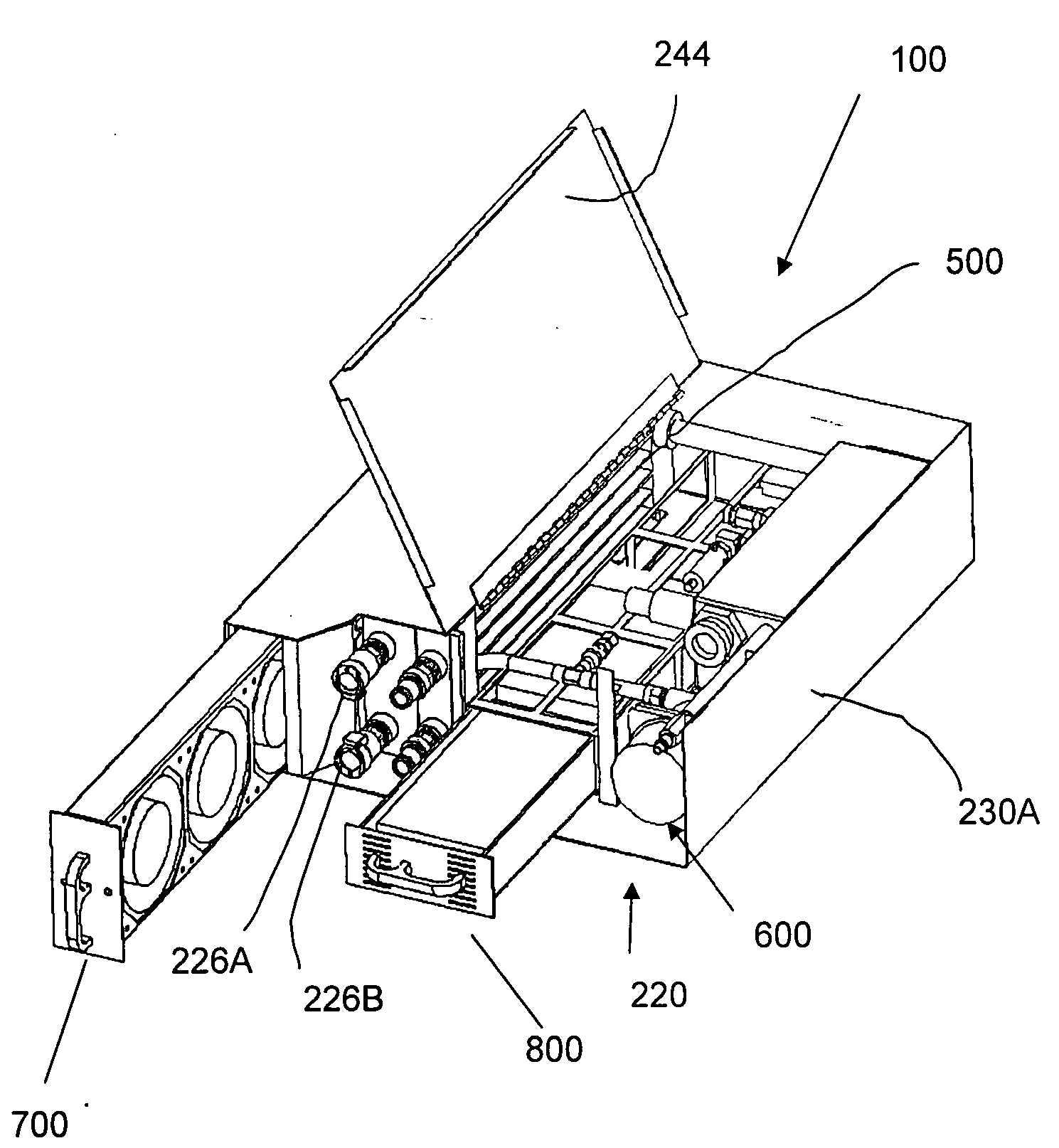
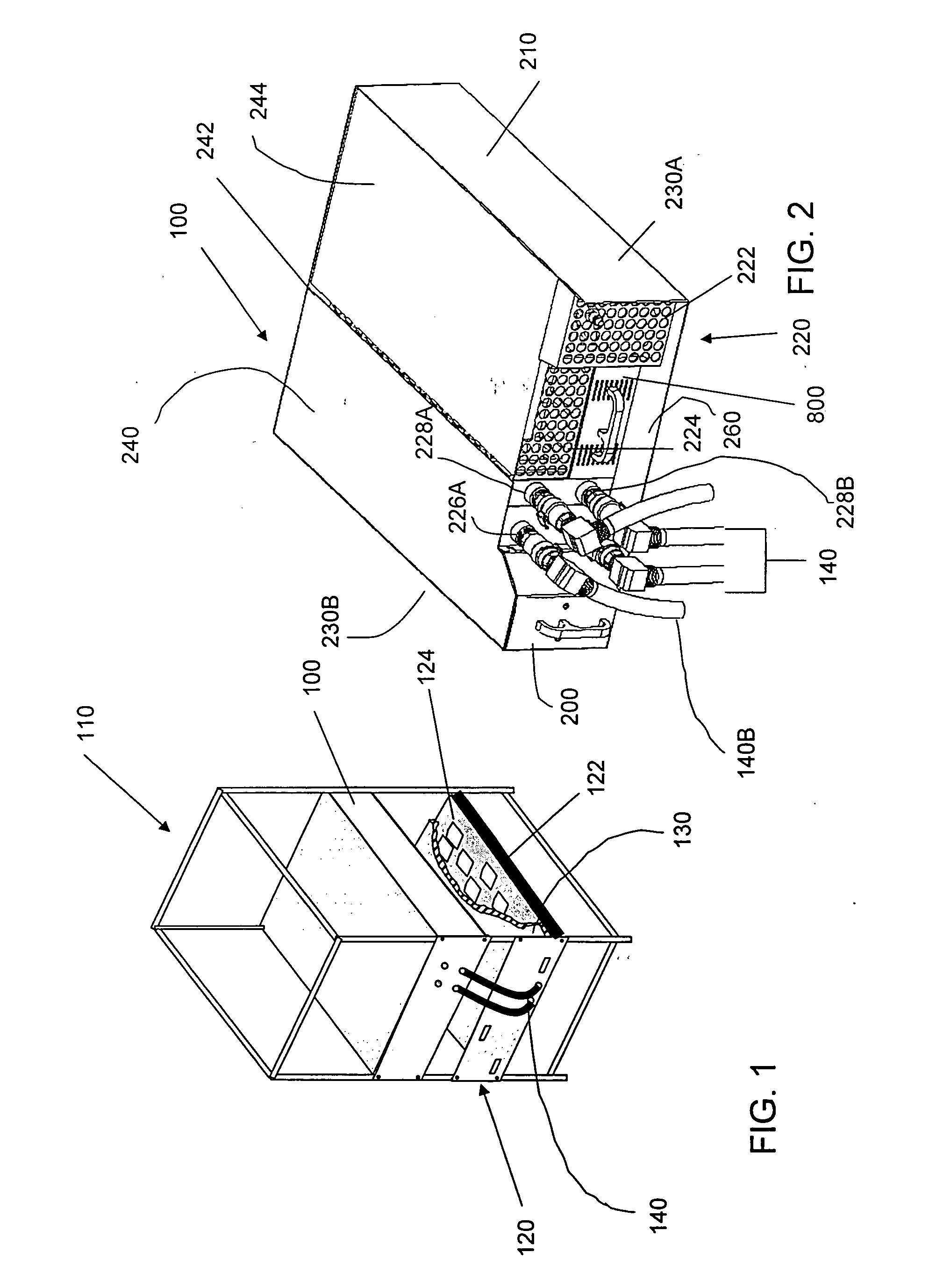
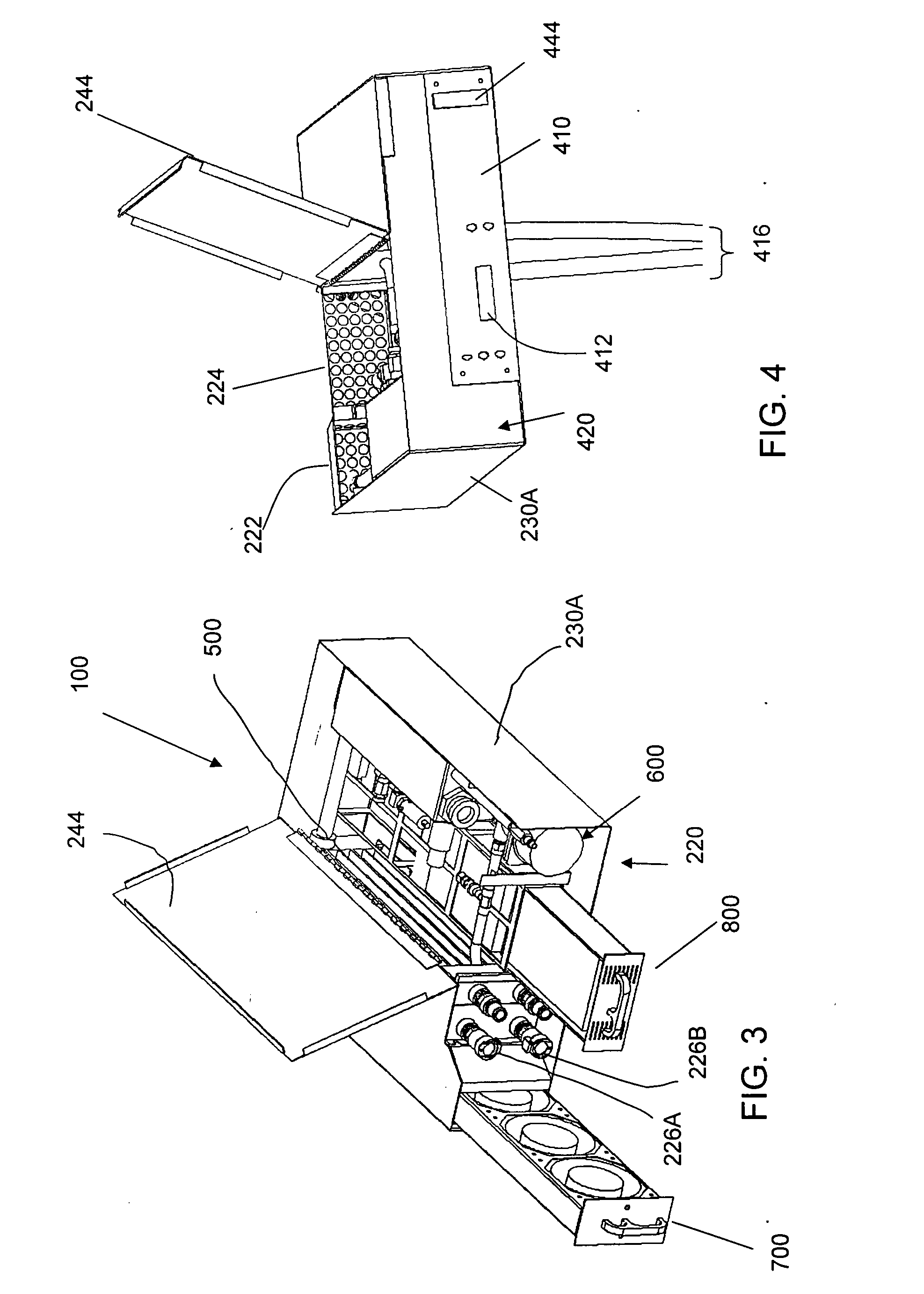
[0034] Case 210 has a face 220. In a preferred embodiment, all access to chiller assembly 100 will be made through face 220 during normal operation of chiller assembly 100.

[0035] Pump cover 222 may be removed to provide access to pump and motor assembly 600, which is described in greater detail below in connection with FIG. 6. Power supply tray assembly 800 may be removed through face 220. Power supply tray 800 is described in greater detail below in connection with FIG. 8.

[0036] Fluid outlets 228A and 228B provide a connection to two cold plates. Here fluid outlet 228B is shown connected to one of the hoses 140. Fluid inlets 226A and 226B provide a return path for the connections to cold plates.

[0037] Fan assembly 700 may also be removed from chiller assembly 100 through face 220. Fan assembly 700 is described below in greater detail in connection with FIG. 7.

[0038] Cover 224 covers remaining space in face 220. In the preferred embodiment cover 224 is made of a perforated metal....


PUM


Abstract

A chiller assembly shaped for use in a standard electronics rack. The chiller has a low profile, and is capable of being made to occupy less than 5 rack units. The chiller is modular, with subassemblies positioned to allow easy removal for maintenance. The fan and power supply are made as replaceable subassemblies that can be inserted or removed from the front of the unit without any special tools. The pump is made with a magnetically coupled motor, allowing the motor to be easily removed for service or replacement. The motor is also accessible from the front panel of the assembly.

Description

BACKGROUND OF INVENTION [0001] 1. Field of Invention [0002] This invention relates generally to electronic assemblies and more specifically to thermal management in an electronic assembly. [0003] 2. Discussion of Related Art [0004] Many modern electronic systems are constructed by attaching electronic components to printed circuit boards. The printed circuit boards are then installed into a mechanical chassis (i.e. subassembly), which allows them to be installed into a larger frame. In some cases, multiple boards are installed and electrically interconnected within a chassis. The frame, also called the “rack”, provides the mechanical support for each chassis. [0005] The frame also allows each chassis to be electrically interconnected. The boards in one chassis can be electrically interconnected to the boards within other chassis through the same frame. In the most common frame configurations, the printed circuit boards are installed parallel to the ground. The common alternative is ...

Claims


Application Information

Patent Timeline
IPC IPC(8): F28D1/053G06F1/20H05K7/20
CPCF28D1/0535H05K7/20781F28D2021/0029
Inventor PFAHNL, ANDREAS C.
Owner AMPHENOL CORP
Why Eureka
Try Eureka