Finned Jackets for lan cables

Inactive Publication Date: 2005-06-23
COMMSCOPE SOLUTIONS PROPERTIES
View PDF12 Cites 51 Cited by
  • Summary
  • Abstract
  • Description
  • Claims
  • Application Information

AI Technical Summary

Benefits of technology

[0017] It is an object of the present invention to provide a cable with a jacket configuration, which improves the alien crosstalk and attenuation performance of the cable, as compared to existing cables.
[0018] It is an object of the present invention to provide a cable with an improved attenuation and crosstalk performance, which meets or surpasses the minimum standards to qualify as a telecommunications cable, such as UL Subject 444, and EIA/TIA 568.
[0019] These and other objects are accomplished by a cable including a plurality of conductors housed inside a jacket. A plurality of protrusions extends away from a

Problems solved by technology

Such compounds have inferior dielectric properties.
However, adding a shielding layer to a cable complicates the manufacturing process, changes the telecommunication network to incorporate grounding and requiring different interconnection components, and greatly increases the cost of the cable and the network.
However, this solution also suffers drawb

Method used


Image

  • Finned Jackets for lan cables
  • Finned Jackets for lan cables
  • Finned Jackets for lan cables

Examples


first embodiment

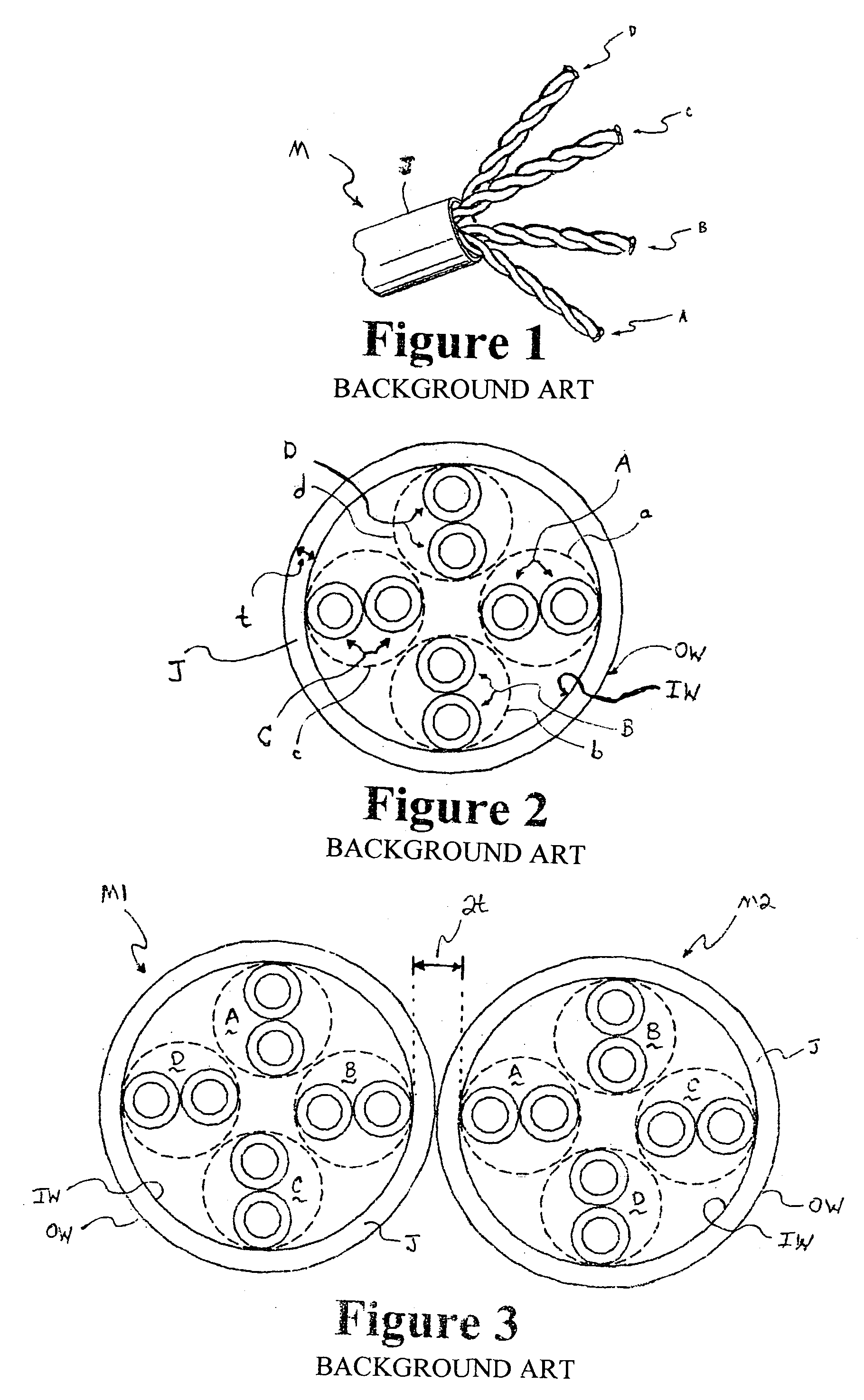
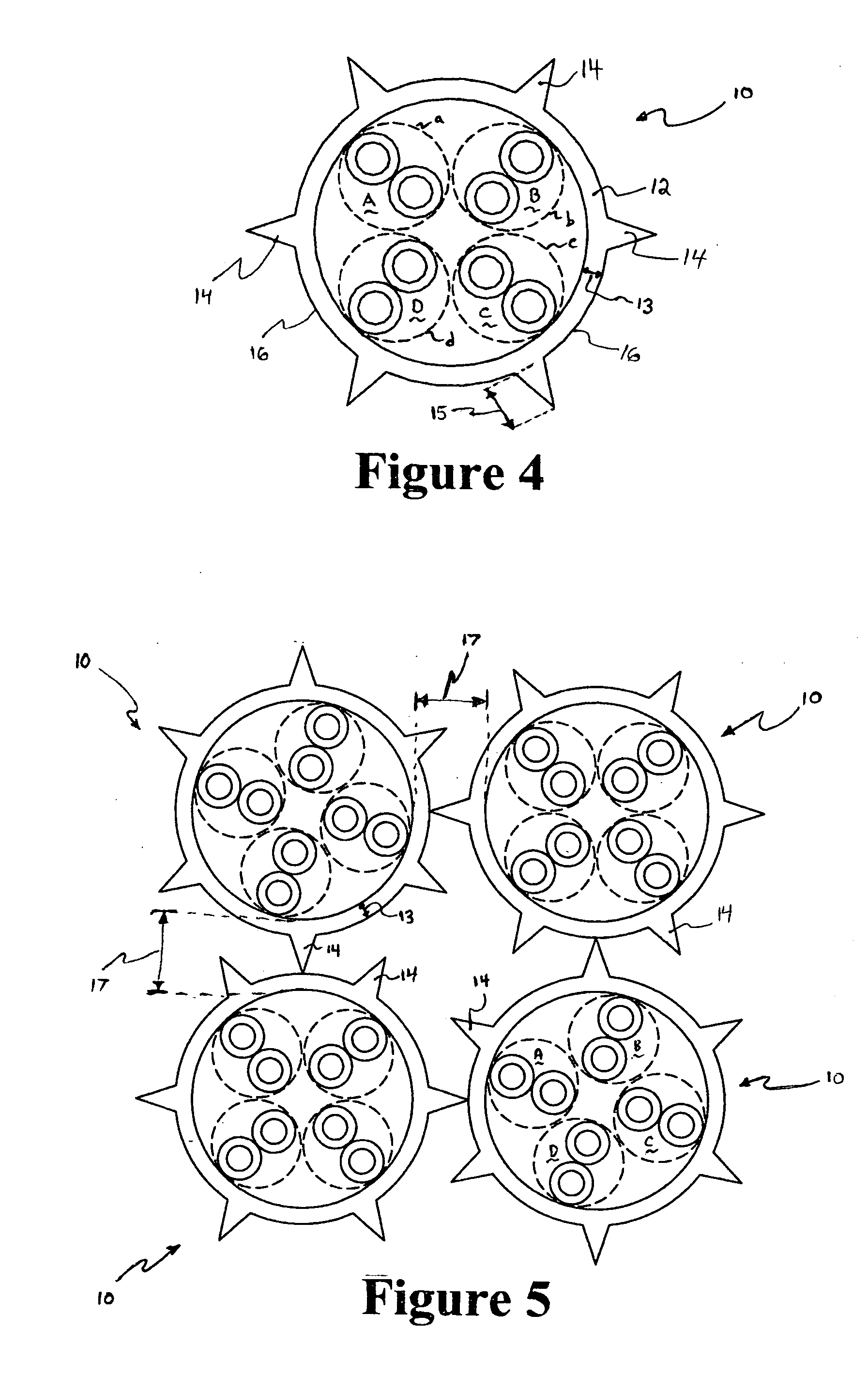
[0033]FIG. 4 is a cross sectional view of a cable 10, in accordance with the present invention. The cable 10 includes the first, second, third and fourth twisted wire pairs A, B, C and D, which are the same or similar to the twisted wire pairs illustrated in FIGS. 1-3.

[0034] The cable 10 includes a jacket 12. The jacket 12 may be formed of a smoke or fire retardant material, such as a PVC compound. A thickness 13 of the jacket 12 is preferably about 20 mils.

[0035] A plurality of protrusions 14 is formed on an outer circumferential wall 16 of the jacket 12. The protrusions 14 have a triangular shape and a thickness 15, which is preferably about 30 mils. The protrusions 14 extend radially outward, away from a center of the cable 10. The protrusions 14 may be integrally formed with the jacket 12 during an initial extrusion process to form the jacket 12.

[0036] Although FIG. 4 illustrates six protrusions 14 integrally formed with the jacket 12, it should be noted that more or less prot...

second embodiment

[0039]FIG. 6 is a cross sectional view of a cable 20, in accordance with the present invention. The cable 20 includes the first, second, third and fourth twisted wire pairs A, B, C and D, which are the same or similar to the twisted wire pairs illustrated in FIGS. 1-3.

[0040] The cable 20 includes a jacket 22. The jacket 22 may be formed of a smoke or fire retardant material, such as a PVC compound. A thickness 23 of the jacket 22 is preferably about 20 mils.

[0041] A plurality of protrusions 24 is formed on an outer circumferential wall 26 of the jacket 22. The protrusions 24 have a rectangular shape and a thickness 25, which is preferably about 30 mils. The protrusions 24 extend radially outward, away from a center of the cable 20. The protrusions 24 may be integrally formed with the jacket 22 during an initial extrusion process to form the jacket 22.

[0042] Although FIG. 6 illustrates six protrusions 24 integrally formed with the jacket 22, it should be noted that more or less pro...

third embodiment

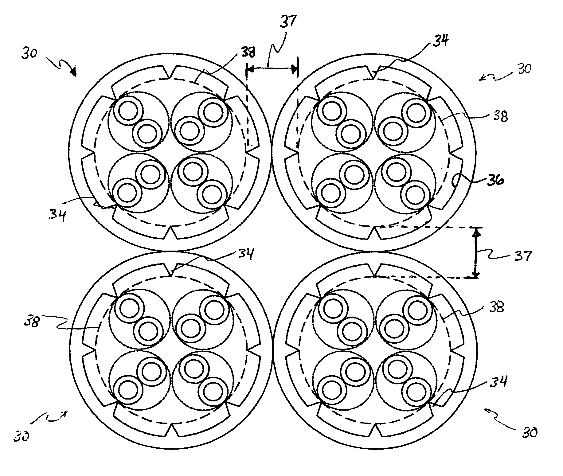
[0045]FIG. 8 is a cross sectional view of a cable 30, in accordance with the present invention. The cable 30 includes the first, second, third and fourth twisted wire pairs A, B, C and D, which are the same or similar to the twisted wire pairs illustrated in FIGS. 1-3.

[0046] The cable 30 includes a jacket 32. The jacket 32 may be formed of a smoke or fire retardant material, such as a PVC compound. A thickness 33 of the jacket 32 is preferably about 20 mils.

[0047] A plurality of protrusions 34 is formed on an inner circumferential wall 36 of the jacket 32. The protrusions 34 have a triangular shape and a thickness 35, which is preferably about 20 mils. The protrusions 34 extend radially inward, toward a center of the cable 30. The protrusions 34 may be integrally formed with the jacket 32 during an initial extrusion process to form the jacket 32.

[0048] Although FIG. 8 illustrates eight protrusions 34 integrally formed with the jacket 32, it should be noted that more or less protru...


PUM


Abstract

A cable includes a plurality of twisted wire pairs housed inside a jacket. A plurality of protrusions extend away from a circumferential surface of the jacket. The protrusion may extend radially outward from an outer circumferential surface of the jacket, or may extend radially inward from an inner circumferential surface of the jacket toward a center of the cable. The protrusions ensure that the twisted wire pairs of one cable are well-distanced from the twisted wire pairs of another cable when two cables are placed adjacent to one another and improve the dielectric properties of the jacket. The cable can be designed to meet all of telecommunication cabling industry regulations and standards, and demonstrates improved alien crosstalk and attenuation characteristics even at high data bit rates.

Description

BACKGROUND OF THE INVENTION [0001] 1. Field of the Invention [0002] The present invention relates to a cable employing a plurality of twisted wire pairs. More particularly, the present invention relates to a jacket for housing the plurality of twisted wire pairs, which reduces the likelihood of transmission errors because of reduced alien crosstalk, interference from an adjacent cable, and reduced signal attenuation, and hence allows for a relatively higher bit rate transmission. [0003] 2. Description of the Related Art [0004] Along with the greatly increased use of computers for homes and offices, there has developed a need for a cable, which may be used to connect peripheral equipment to computers and to connect plural computers and peripheral equipment into a common network. Today's computers and peripherals operate at ever increasing data transmission rates. Therefore, there is a continuing need to develop a cable, which can operate substantially error-free at higher bit rates, ...

Claims


Application Information

Patent Timeline
IPC IPC(8): H01B7/00H01B7/18H01B11/00H01B11/04H01B13/00
CPCH01B11/04H01B7/184H01B7/18
Inventor PARKE, DANIEL J.WIEBELHAUS, DAVID A.
Owner COMMSCOPE SOLUTIONS PROPERTIES
Why Eureka
Try Eureka