Electric power steering apparatus

a technology of electric power steering and rack assist, which is applied in the direction of electrical steering, steering parts, power driven steering, etc., can solve the problems of large engine driving loss, several or ten horsepower, and inability to reduce gas mileage, so as to reduce the weight of the roller holder and improve the efficiency of the power steering apparatus. , the effect of small swing amoun

Inactive Publication Date: 2005-06-23
NSK LTD
View PDF1 Cites 62 Cited by
  • Summary
  • Abstract
  • Description
  • Claims
  • Application Information

AI Technical Summary

Benefits of technology

[0008] The present invention has been made in view of the above-described situation. An object of the present invention is to provide a rack assist type electric power steering apparatus in which tension adjustment of a belt in the power transmission mechanism can be carried out appropriately and easily.

Problems solved by technology

However, this type of power steering apparatus suffers from large engine driving loss (as much as several or ten horsepower in the maximum load state) due to constant driving of the hydraulic pump.
Therefore, it is difficult to use this type of power steering apparatus in mini-sized motor vehicle with a small engine displacement, and even in the case of vehicles with a relatively large displacement, a considerable decrease in gas mileage is inevitable.
If this looseness exceeds a certain degree, slippage will occur between the belt and the pulleys in the case that the belt is a V-belt or a flat belt, or tooth skip will occur between the belt and the pulleys, so that power will not be transmitted appropriately and damages such as burning or tooth drop will occur in the belt.
However, in the case of the power transmission mechanism of the EPS, since the rotation direction of the drive pulley changes depending on the steering direction changed by the driver, if the tension pulley is pressed against the tension side web, the tension pulley will be moved back by the tension of the tension side web to cause a delay in power transmission to the driven pulley.
This causes the problem that steering assist cannot be effected smoothly.
This disadvantage also occurs in the case that tensioners are provided on both sides of the belt since the tension pulleys are moved back due to the tension of the tension side web.

Method used


Image

  • Electric power steering apparatus
  • Electric power steering apparatus
  • Electric power steering apparatus

Examples


first embodiment

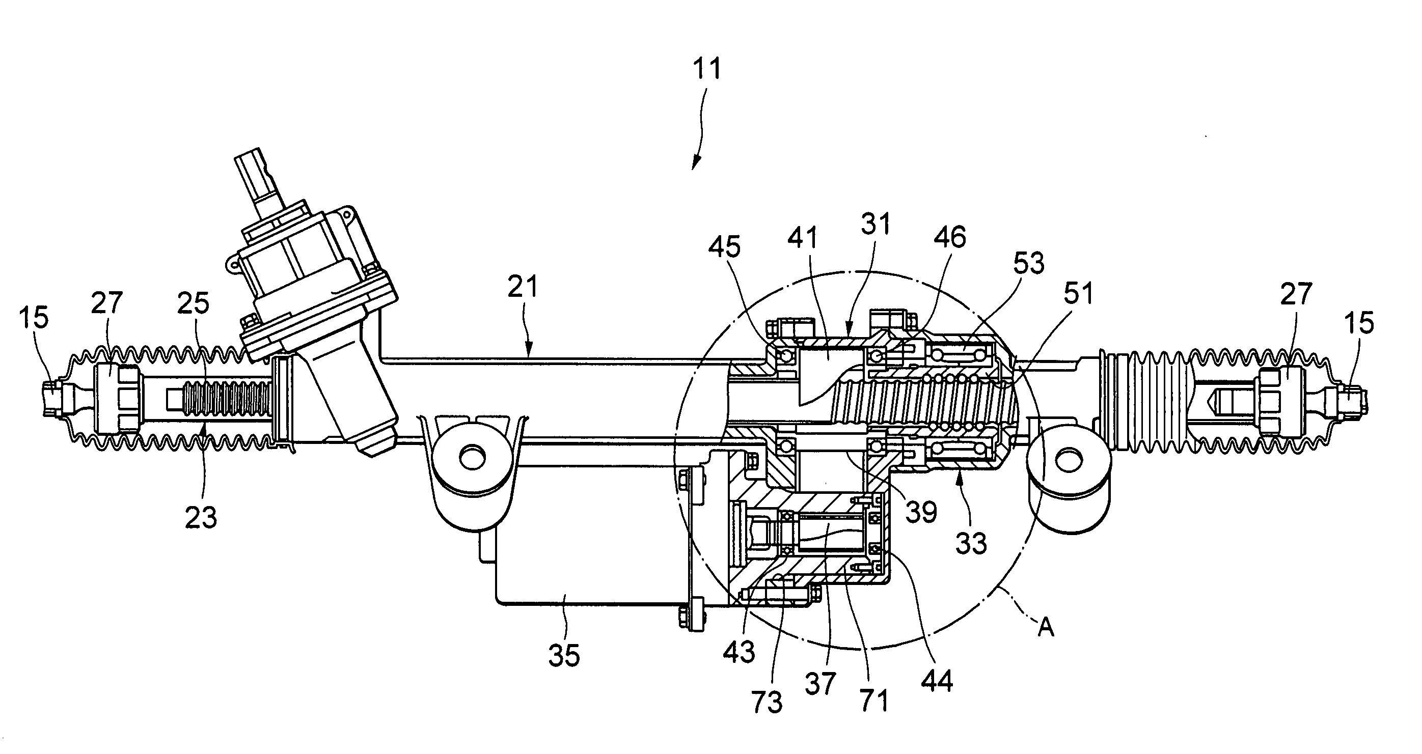
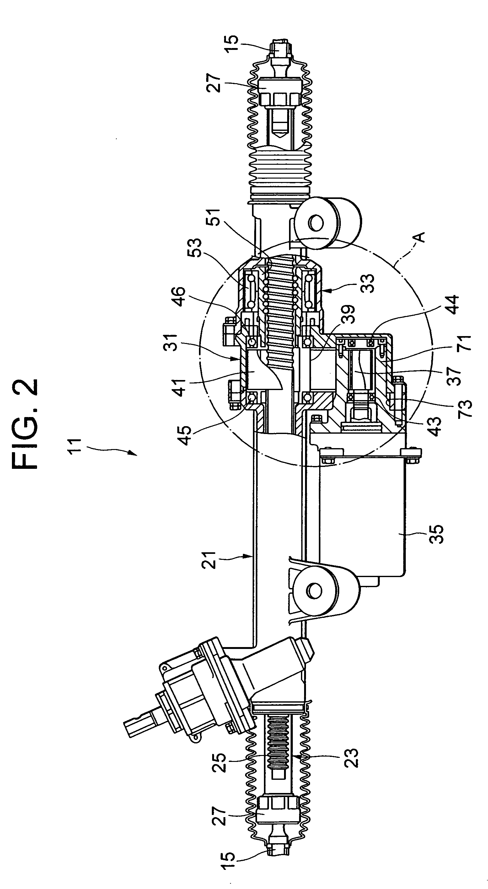
[0092]FIG. 2 is a longitudinal cross sectional view showing the steering gear 11 according to the present invention. FIG. 3 is an enlarged view showing portion A in FIG. 2. FIG. 4 is a cross sectional view taken along line B-B in FIG. 3. FIG. 5 is a cross sectional view taken along line C-C in FIG. 3. The member designated by reference sign 21 in FIG. 2 is a rack and pinion housing that constitutes the steering gear case, which holds a rack shaft 23 and a pinion (not shown) that compose the rack and pinion mechanism. On the rack shaft 23, a rack 25 engaging the pinion is formed in the left side portion in FIG. 2. At the left and right ends (in FIG. 2) of the rack shaft 23, spherical joints 27 that support the tie rods 25 in a swingable manner are secured.

[0093] The outer hull of the power assist mechanism is composed of a belt housing 31 secured to the right side (in FIGS. 2 and 3) of the rack and pinion housing 21 by bolts and a ball screw housing 33 secured to the right side (in F...

second embodiment

[0123]FIG. 23 is a longitudinal cross sectional view showing a steering gear according to the present invention. FIG. 24 is an enlarged view showing portion A in FIG. 23. FIG. 25 is a cross sectional view taken along line B-B in FIG. 24. FIG. 26 is a cross sectional view taken along line C-C in FIG. 24. FIG. 27 is a cross sectional view taken along line D-D in FIG. 24. The member designated by reference sign 21 in FIG. 23 is a rack and pinion housing that constitutes the steering gear case, which holds a rack shaft 23 and a pinion (not shown) that compose the rack and pinion mechanism. On the rack shaft 23, a rack 25 engaging the pinion is formed in the left side portion in FIG. 23. At the left and right ends (in FIG. 23) of the rack shaft 23, spherical joints 27 that support the tie rods 25 in a swingable manner are secured.

[0124] The outer hull of the power assist mechanism is composed of a belt housing 31 secured to the right side (in FIGS. 23 and 24) of the rack and pinion housi...

third embodiment

[0144] Next, the present invention will be described.

[0145]FIG. 33 is a longitudinal cross sectional view showing a steering gear according to the third embodiment. FIG. 34 is an enlarged view of part A in FIG. 33. FIG. 35 is a cross sectional view taken along line B-B in FIG. 34. FIG. 36 is a cross sectional view taken along line C-C in FIG. 34. Referring to FIG. 33, a rack shaft 23 and a pinion (not shown) that compose a rack and pinion mechanism are held in the interior of a rack and pinion housing 21 that constitutes a steering gear case. On the rack shaft 23, a rack 25 engaging the pinion is formed in the left side portion in FIG. 33. At the left and right ends (in FIG. 33) of the rack shaft 23, spherical joints 27 that support the tie rods 25 in a swingable manner are secured.

[0146] The outer hull of the power assist mechanism is composed of a belt housing 31 secured to the right side (in FIGS. 33 and 34) of the rack and pinion housing 21 by bolts and a ball screw housing 33 ...


PUM


Abstract

In a rack assist type electric power steering apparatus which is provided with a ball screw mechanism having a rack shaft and a ball nut, the ball screw mechanism supporting the rack shaft in such a way that the rack shaft can be moved in the axial direction by rotation of the ball nut, a drive pulley rotating integrally with the shaft of an electric motor for power aid, a driven pulley rotating integrally with said ball nut and a belt looped around the drive pulley and the driven pulley, adjustment of the tension of the belt can be effected appropriately and easily.

Description

TECHNICAL FIELD [0001] The present invention relates to a rack assist type electric power steering apparatus in which a belt type power transmission mechanism is employed. BACKGROUND ART [0002] In the steering system of vehicles, so-called power steering apparatuses for assisting the steering operation by means of an external power source are widely used. Conventionally, vane type hydraulic pumps have been used as the power source of the power steering apparatuses. In many cases, the hydraulic pump is driven by the engine. However, this type of power steering apparatus suffers from large engine driving loss (as much as several or ten horsepower in the maximum load state) due to constant driving of the hydraulic pump. Therefore, it is difficult to use this type of power steering apparatus in mini-sized motor vehicle with a small engine displacement, and even in the case of vehicles with a relatively large displacement, a considerable decrease in gas mileage is inevitable. [0003] In v...

Claims


Application Information

Patent Timeline
Patent Type & Authority Applications(United States)
IPC IPC(8): B62D5/04F16H7/02F16H7/08F16H7/14
CPCB62D5/0424F16H7/023F16H2025/2096F16H2007/088F16H7/14
Inventor CHIKARAISHI, KAZUO
Owner NSK LTD
Why Eureka
Try Eureka