
Handheld blower

a blower and hand-held technology, applied in the direction of machines/engines, cleaning equipment, and turf growing, can solve the problems of accidental operation of the stop switch b>5/b>b against the operator's intention, difficult to maintain the end pipe constant in one position, and difficult to continue the operation. , to prevent accidental stop of the blower during use, the effect of reducing the load

Inactive Publication Date: 2005-06-23
MAKITA NUMAZU CORP
View PDF13 Cites 21 Cited by
  • Summary
  • Abstract
  • Description
  • Claims
  • Application Information

AI Technical Summary

Benefits of technology

"The present invention provides a handheld blower with a structure that prevents accidental stop of the blower during use and enables the operator to keep orienting an end pipe thereof in a desired direction while mitigating the load exerted on the operator's thumb on the grip. The handheld blower includes a grip, a stop switch, and a thumb rest. The thumb rests on a surface of the grip that is positioned forward of the center of the impeller when the blower is placed on the ground and inclined at an angle within an angle range that is from a reference line parallel to the ground to a plane perpendicular to the blowing direction. The handheld blower also includes switch guards on the grip at both sides of the stop switch to prevent the thumb from touching the switch. The thumb rests on the switch guards when the grip is held by the operator's fingers in a suspended manner. The handheld blower provides a comfortable grip, reduces fatigue, and ensures proper orientation of the end pipe during operation."

Problems solved by technology

However, in the case where the thumb TH on the upper face of the grip 5 is positioned along an extension line of the widthwise center line of the stop switch 5B on the front of the grip 5, depending on the location of the stop switch 5B, particularly when the stop switch 5B is of the type which is slid to the front or back of the grip to stop the blower, there is a danger that the stop switch 5B is accidentally operated against the operator's intention during the operation.
If the stop switch is provided with surface irregularities for preventing slippage, the operator may suffer pain on the thumb TH because of the force of reaction from the protruded parts of the irregularities, and may find it hard to continue the operation.
As the supporting point does not match the center of the gravity, a moment is created at the gripping position, making it hard to maintain the end pipe constantly in one position.
In order to keep the end pipe 6 directed to a certain position on the ground, the thumb on the grip plays a great role, because of which a large load is applied to the thumb, causing the operator's fatigue.

Method used


Image

  • Handheld blower
  • Handheld blower
  • Handheld blower

Examples


Embodiment Construction

[0034] Preferred embodiments of the present invention will be hereinafter described with reference to the accompanying drawings

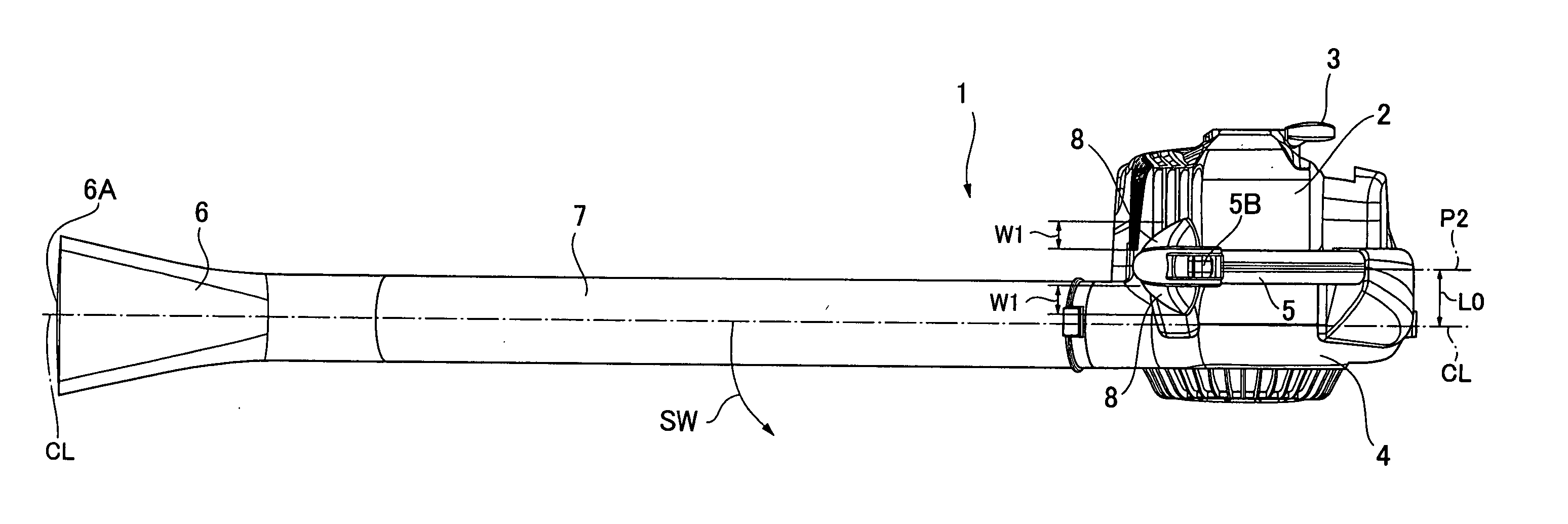
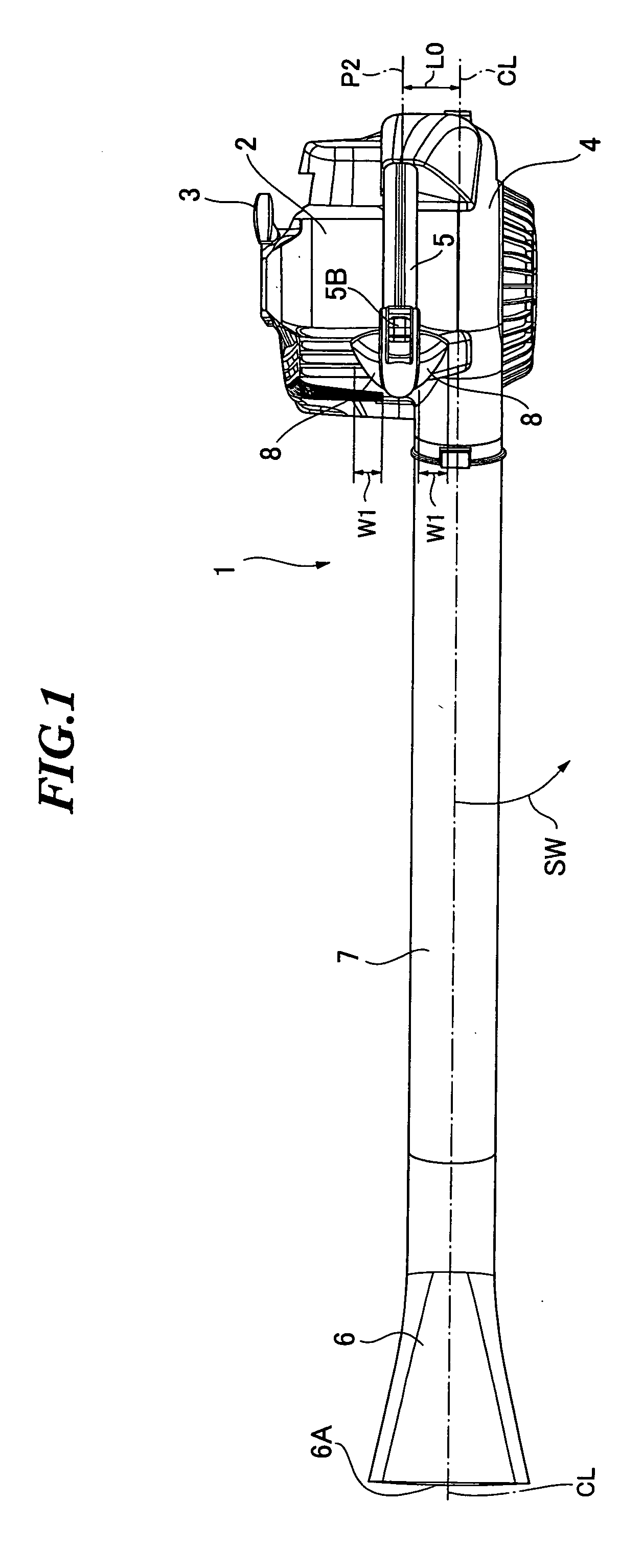
[0035]FIG. 1 is a plan view of a handheld blower 1 according to one embodiment of the present invention.

[0036] The blower 1 includes an engine (not shown) as the power source accommodated in an engine cover 2. The engine is started by pulling a recoil starter knob 3.

[0037] A casing 4 accommodates an impeller (not shown) which is attached to the output shaft of the engine. The engine cover 2 and the casing 4 together form a drive unit of the blower 1.

[0038] The engine cover 2 and the casing 4 are both molded parts which are produced using a split mold. A grip 5 is provided on top of the engine cover 2 and the casing 4. The structure of the grip 5 will be described in more detail later.

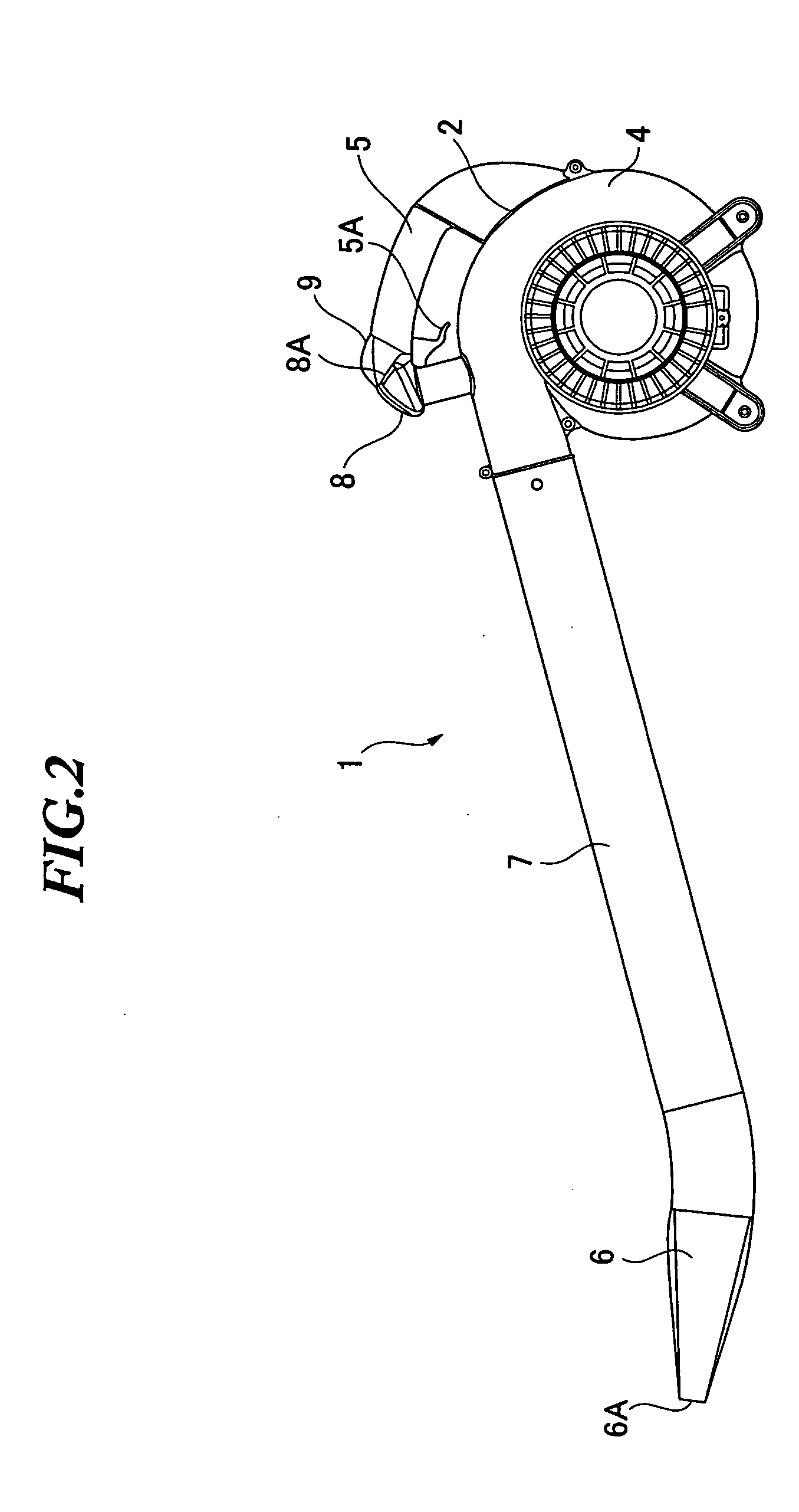
[0039] As shown in FIG. 2, the casing 4 accommodating the impeller inside communicates with an end pipe 6, which has an opening 6A at the end, through a coupling pipe 7.

[0...


PUM


Abstract

A handheld blower is provided with an end pipe having a blowing opening at a distal end thereof, the end pipe being coupled to the upper half side of an impeller case and extended in a tangential direction of the impeller. The blower further includes a grip grasped by an operator's fingers to support the blower in a suspended manner, a stop switch provided on an extension line of a widthwise center line of the grip, and a thumb rest extending to a side of the grip from near the stop switch for receiving the operator's thumb. Thus, the handheld blower can prevent accidental stop of the blower, which is caused by an inadvertent touch to the stop switch with the thumb, during use, and enables the operator to keep orienting the end pipe to a desired direction while mitigating the load on the thumb on the grip.

Description

BACKGROUND OF THE INVENTION [0001] The present invention relates to a handheld blower and more particularly to an operating part of the blower. [0002] The present application claims priority from Japanese Patent Application No. 2003-423187, the disclosure of which is incorporated herein by reference. [0003] A handheld blower as shown, for example, in Japanese Patent Application Laid-Open No. Hei 8-200064 is known as an apparatus for cleaning operation in which scattered lightweight rubbish such as leaves on the ground are collected in one place by blowing. [0004] Referring to FIG. 5 which shows one embodiment of the present invention, a handheld blower generally includes an engine case 2 accommodating an engine which is the power source, an impeller coupled to the output shaft of the engine, a connection pipe 7 attached to the casing 4 of the impeller in a tangential direction thereof, and an end pipe 6 at the other end of the connection pipe 7, with an opening 6A for the blowing op...

Claims


Application Information

Patent Timeline
Patent Type & Authority Applications(United States)
IPC IPC(8): A47L5/14F02B63/06A47L9/32E01H1/08F02D11/02H01H9/06
CPCA47L5/14A47L9/32A01G1/125H01H9/06E01H1/0809A01G20/47
Inventor WATANABE, MITSUNORIKUBOTA, HIROSHINODA, HIROYUKI
Owner MAKITA NUMAZU CORP
Learn More