Methods for making internal die filters with multiple passageways which are fluidically in parallel

a technology of fluid flow and die filter, applied in the direction of printing, paper/cardboard articles, etc., can solve the problems of needing to be carefully controlled, and achieve the effect of preventing overetching or underetching of critical features

Inactive Publication Date: 2005-06-23
XEROX CORP
View PDF5 Cites 4 Cited by
  • Summary
  • Abstract
  • Description
  • Claims
  • Application Information

AI Technical Summary

Benefits of technology

[0009] A second limitation of the fabrication process described in the incorporated 748 patent is that the some of the chemical etch steps need to be carefully controlled in terms of bath composition, temperature, and / or duration, in order to prevent overetching or underetching of the critical features.

Problems solved by technology

One limitation of the fabrication process described in the incorporated 748 patent is that the material of the device surrounding the fluid passageways and filter pores needs to be single crystal silicon or other material compatible with orientation-dependent chemical etching.
A second limitation of the fabrication process described in the incorporated 748 patent is that the some of the chemical etch steps need to be carefully controlled in terms of bath composition, temperature, and / or duration, in order to prevent overetching or underetching of the critical features.

Method used


Image

  • Methods for making internal die filters with multiple passageways which are fluidically in parallel
  • Methods for making internal die filters with multiple passageways which are fluidically in parallel
  • Methods for making internal die filters with multiple passageways which are fluidically in parallel

Examples


Embodiment Construction

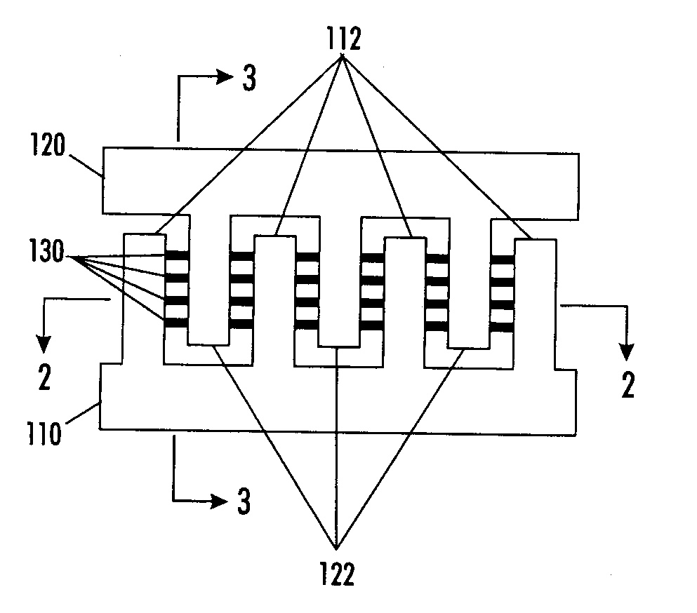
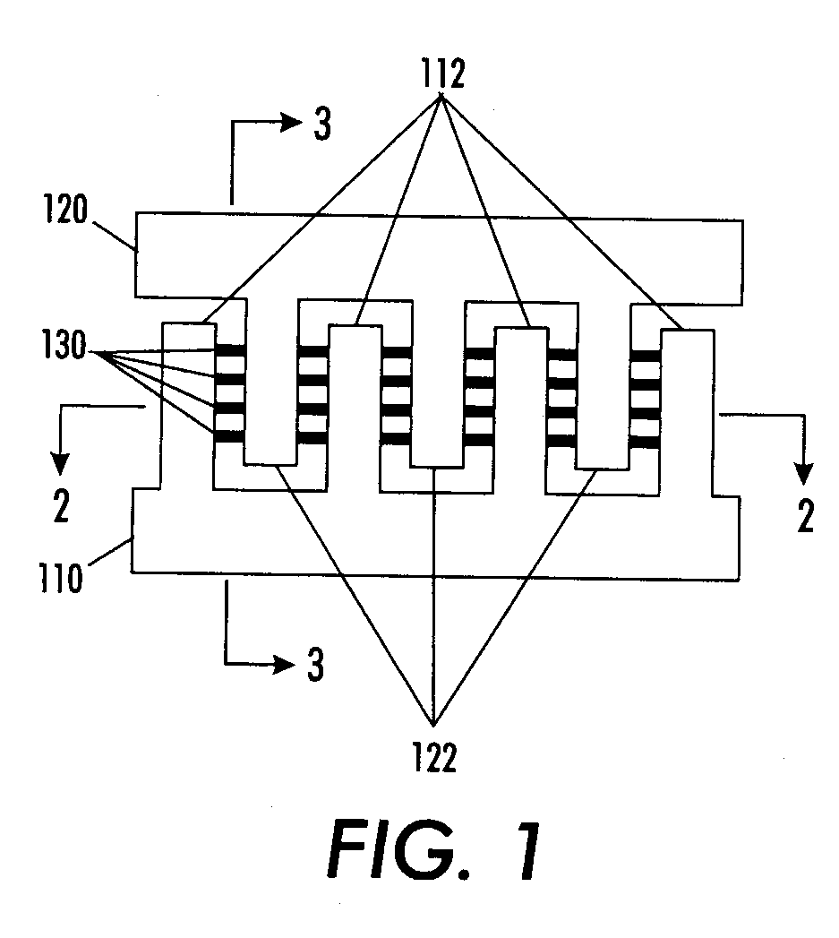
[0040]FIG. 1 is a top plan view of a first exemplary embodiment of an internal filter 100 having interleaved comb fluid pathways 110 and 120 connected by multiple sets of filter pores 130 in accordance with this invention. As shown in FIG. 1, the inlet side passageway 110 has a plurality of extensions 112 that are configured in a comb pattern and may be placed, for example, near the fluid inlet to the microfluidic device. The outlet side passageway 120 has a plurality of extensions 122 that are also configured in a comb pattern. The fluid passes from the extensions 112 of the inlet side passageway 110 to the extensions 122 of the outlet side passageway 120 through the filter pores 130.

[0041] The fluid in the outlet side passageway 120 has a substantial number of particles removed relative to the fluid in the inlet side passageway 110. The removed particles are those of a size and shape such that cannot pass through the filter pores 130. The fluid may then pass from the outlet side ...


PUM

PropertyMeasurementUnit
sizeaaaaaaaaaa
impedanceaaaaaaaaaa
lengthaaaaaaaaaa

Abstract

An internal filter includes a lower substrate and an upper substrate. Fluid passages are formed by etching grooves into the surface(s) of the upper and/or lower substrates, and/or in one or more intermediate layers. The filter pores extending between the fluid passages are formed by etching second grooves that fluidly connect the fluid passages. Two or more sets of the one or two intermediate layers can be implemented to provide additional filter passages and/or pores. Each set can be connected to a separate fluid source and/or a separate microfluidic device. In another internal filter, the inlet and outlet passages and the filter pores are formed on the same upper or lower substrate. The inlet and outlet passages are partially formed in a first step. In a second step, the inlet and outlet passages are completed at the same time that the filter pores are formed.

Description

BACKGROUND OF THE INVENTION [0001] 1. Field of Invention [0002] This invention relates to systems and methods for fabricating internal die filters. [0003] 2. Description of Related Art [0004] In a wide range of fluid processing applications, including those in the printing, medical, chemical, biochemical, genetic, automotive and energy fields, it is necessary to separate particles out of the fluid. For example, foreign particles or internally-generated particles may interfere with the subsequent intended use of the fluid, by potentially obstructing a small fluidic passageway in a critical region. Alternatively, the particles generated in the process may be a desired product. Consequently, it is necessary or desirable to capture such particles. [0005] In particular, there is a class of devices, called microfluidic devices, in which a fluid enters the device and is then processed in some way by the device. Such microfluidic devices typically have an inlet for the fluid, a fluid proces...

Claims


Application Information

Patent Timeline
Patent Type & Authority Applications(United States)
IPC IPC(8): B31D3/00B41J2/175
CPCB41J2/17563Y10T29/49345Y10T29/49794Y10T29/49798
Inventor KNEEZEL, GARY A.
Owner XEROX CORP
Why Eureka
Try Eureka