Multiple directional wheel

a multi-directional, wheel technology, applied in the field of wheels, can solve the problems of difficult to achieve limited access to the underside, and difficulty in achieving the attachment of the wheel to the object, etc., to achieve the effect of improving mechanical properties, facilitating the adherence of the tire to the bush, and positive engagement of the tire material to the bush

Inactive Publication Date: 2005-06-23
INNOWHEEL PTY LTD
View PDF21 Cites 52 Cited by
  • Summary
  • Abstract
  • Description
  • Claims
  • Application Information

AI Technical Summary

Benefits of technology

[0018] Preferably, the tire is fixedly secured to the bush. For this purpose, the bush may include external surface features which facilitate adherence of the tire to the bush. The surface features may include lateral, longitudinal, and / or diagonal ridges, protrusions optionally hooked, or grooves, recesses and the like to improve the mechanical, positive engagement of the tire material to the bush.

Problems solved by technology

Caster wheels are generally made of multiple components made of different materials and can require a costly and involved manufacturing process.
Moreover, the caster wheel is generally mounted on an object to be moved by a vertical axle making attachment of the wheel to the object sometimes difficult to achieve as access to the underside may be limited and / or awkward.
This manufacturing process is complex as a polyaxled ring is required to be molded separately from that of the remainder of the wheel.

Method used


Image

  • Multiple directional wheel
  • Multiple directional wheel
  • Multiple directional wheel

Examples


Embodiment Construction

[0076] Referring to the Figures, there are shown some, but not the only, embodiments of the invention.

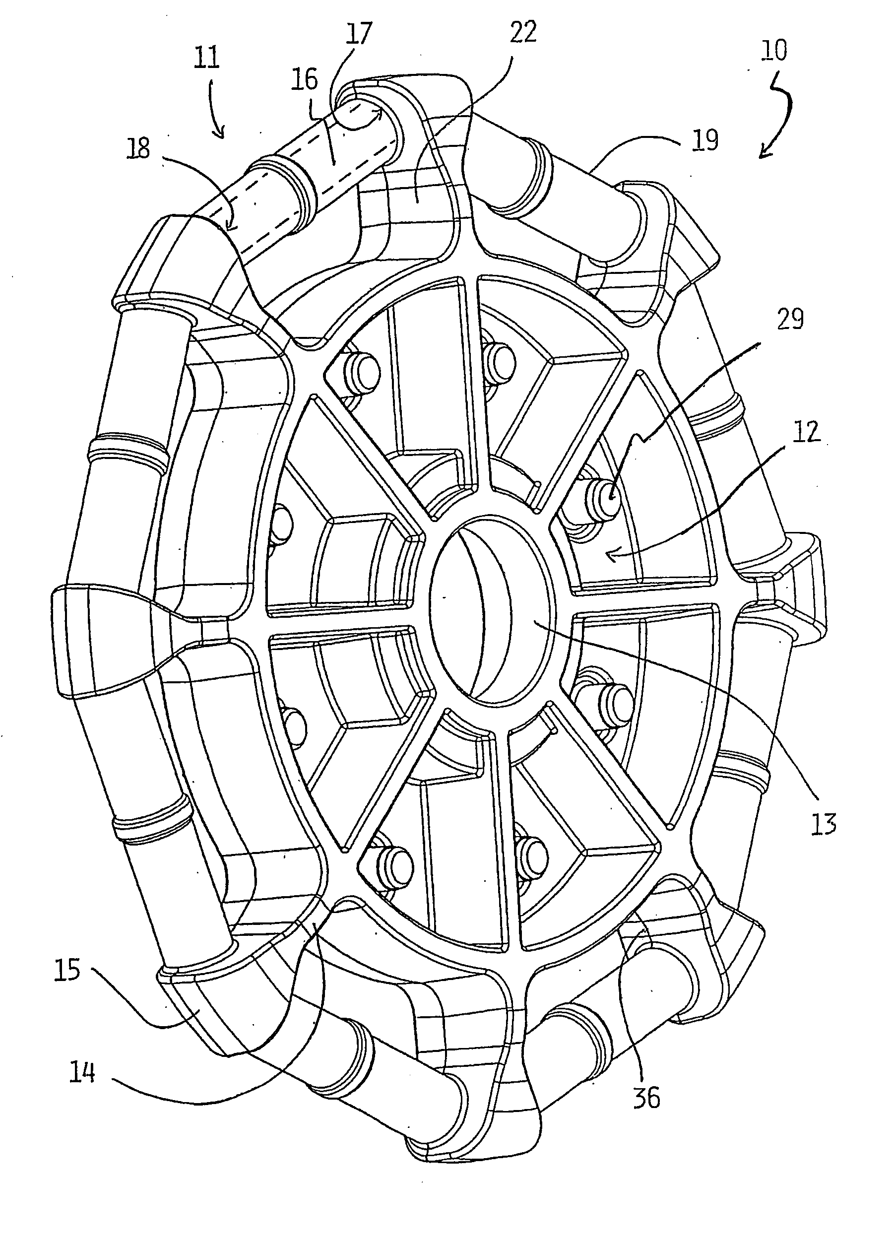
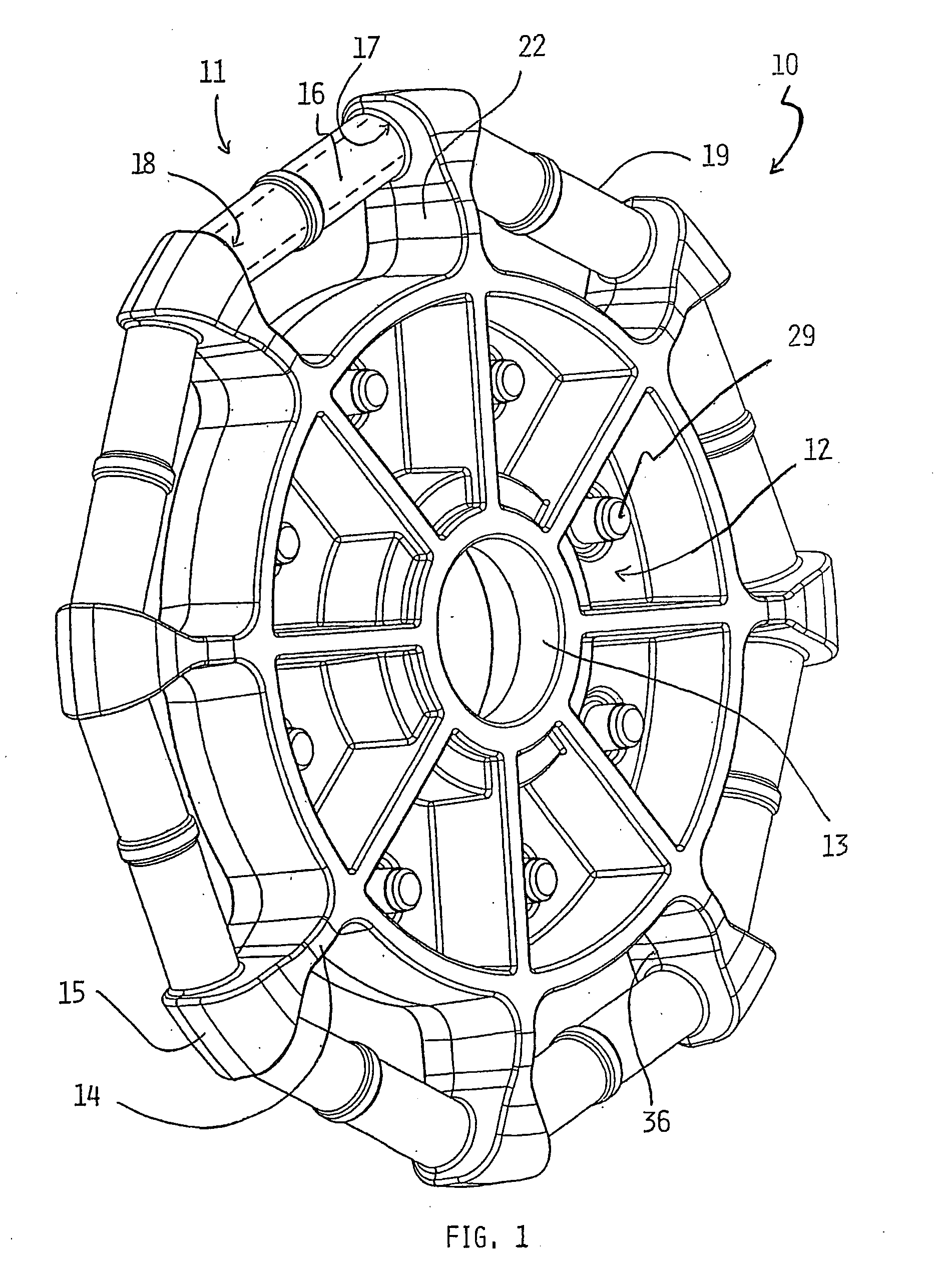
[0077] In FIG. 1, there is shown part of a first wheel 10 which part comprises a frame 11 which includes a central hub 12 defining a bore 13 for a main axle 6 (see FIGS. 4 and 5). Extending radially out from the hub 12 is a plurality of evenly spaced radial arms 14 terminating in diverging head portions 15. The head portion 15 include internal walls 22 which follow the diverging curve of the head portions 15 so that the walls 22 of adjacent radial arms 14 present opposed, square-on faces. Extending between each adjacent pair of head portions 15 is a roller axle 16 represented by broken lines. Each roller axle 16 is a cylindrical roller axle 16 represented by broken lines. Each roller axle 16 is substantially solid, cylindrical and of a consistent cross section along its length. However, at each end 17, 18 of the roller axle 16, the ends 17, 18 are radially spread to ensure that a r...


PUM

PropertyMeasurementUnit
circumferenceaaaaaaaaaa
external surface featuresaaaaaaaaaa
lengthaaaaaaaaaa

Abstract

A multiple directional wheel includes a frame having a central hub rotatable about a main axis, a plurality of roller supports radially spaced from the central hub, and a plurality of rollers evenly spaced around the circumference of the wheel and rotatably mounted on the roller supports. The rollers are preferably rotatable about a corresponding plurality of roller axes aligned in the plane of the wheel and transverse to the main axis. Preferably, the frame is integrally formed in a first molding process and the rollers are formed in place on the wheel about the roller supports in a separate process. In another embodiment there is disclosed a multiple directional wheel including a pair of opposed, separately integrally-formed first and second frames.

Description

[0001] This application is a continuation-in-part, and claims priority, of PCT / AU2003 / 001002 (filed Aug. 7, 2003), which claims priority of Australian Patent Application 2002 950635 (filed Aug. 7, 2002), and this application is also a continuation-in-part, and claims priority, of U.S. patent application Ser. No. 10 / 275,530, which was filed Mar. 20, 2003 as a 371 National Entry of PCT Application PCT / AU01 / 01175 (filed Sep. 20, 2001), which claims priority of Australian Patent Application PR 0296 (filed Sep. 21, 2000). [0002] U.S. patent application Ser. No. 10 / 275,530, issued as U.S. Pat. No. ______ on ______, is incorporated herein by this reference.FIELD OF INVENTION [0003] The invention relates to a wheel. More particularly, this invention relates to a wheel adapted to travel in more than one direction. BACKGROUND [0004] The following description of the prior art and of embodiments in Applicant's previously-filed applications, PCT / AU01 / 01175 and U.S. patent application Ser. No. 10...

Claims


Application Information

Patent Timeline
Patent Type & Authority Applications(United States)
IPC IPC(8): B60B19/12B62B7/04
CPCB60B19/003Y10T16/1853B60B33/0039B60B33/0049B60B2310/204B60B2310/3025B60B2310/318B60B2360/102B60B2360/322B60B2360/324B60B2360/3412B60B2360/348B62B7/04B62B2301/02B60B33/0028
Inventor GUILE, GRAHAM
Owner INNOWHEEL PTY LTD
Why Eureka
Try Eureka