
Ignition coil

a technology of ignition coil and coil body, which is applied in the direction of transformer/inductance details, inductance, induction energy storage installation, etc., can solve the problems of poor magnetic flux density, inability to position permanent magnets, and inability to achieve magnetic efficiency enhancement, and achieve low cost

Active Publication Date: 2005-06-23
MITSUBISHI ELECTRIC CORP
View PDF2 Cites 17 Cited by
  • Summary
  • Abstract
  • Description
  • Claims
  • Application Information

AI Technical Summary

Benefits of technology

[0010] According to this invention, because the contact faces of the first contact position are formed by the first face of the exciting core and the first face of the closed magnetic path forming core, and the contact faces of the second contact position are formed by the second face of the exciting core which is directed to a different direction from the first face and the second face of the closed magnetic path forming core which is directed to a different direction from the first face, and the permanent magnet is arranged between the contact faces of either one of the contact positions. Therefore, dimensional accuracy of both the iron cores is not required as in the conventional device, but the gaps at the contact faces can be minimized at a low cost, and as the results, magnetic efficiency can be advantageously enhanced.

Problems solved by technology

In this case, there has been a problem that a clearance may be formed between the contact faces, or only a part of the contact faces may get in contact, which results in disadvantages in workability and production cost.
Moreover, there has been a problem that positioning of the permanent magnet has become necessary, because it has been difficult to mount the permanent magnet stably on the inclined faces, or an effective sectional area has been made small due to narrowed tip ends of the inclined iron cores, and magnetic flux density has become poor.
In addition, there has been a problem that the first and second gaps cannot be decreased unless dimensional accuracy of the iron cores is controlled, also on occasion of internally contacting the exciting core with the closed magnetic path forming core in a C-shape.

Method used


Image

  • Ignition coil
  • Ignition coil
  • Ignition coil

Examples


embodiment 1

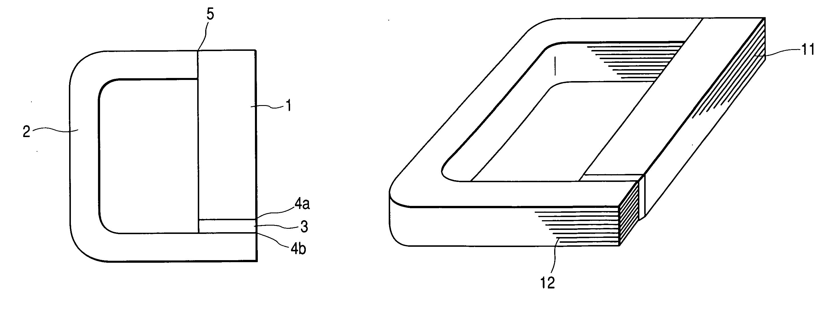
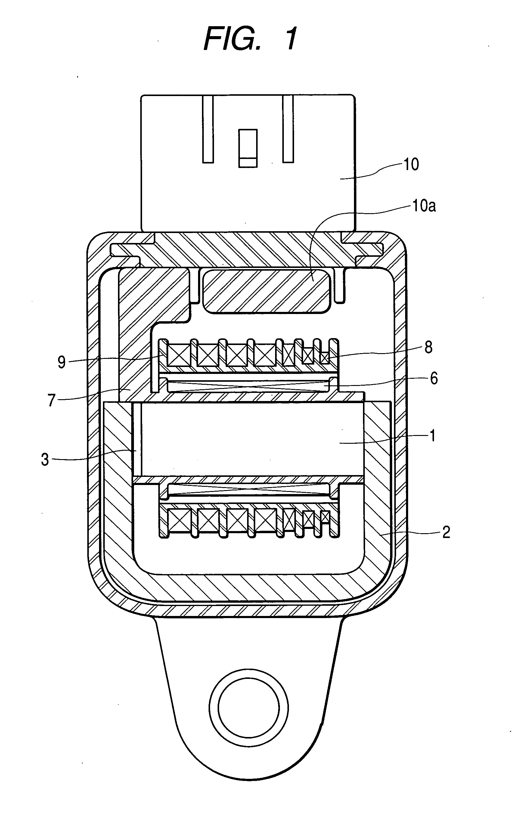
[0018] Referring to the drawings, Embodiment 1 of the ignition coil to which this invention is applied will be described. FIG. 1 is a sectional view showing an entire structure of the ignition coil. In FIG. 1, denoted by numeral 1 is an exciting core in a substantially I-shape which is provided, on its outer periphery, with a primary coil 6 wound around a first bobbin 7, and on its still outer periphery, with a secondary coil 8 wound around a second bobbin 9. A closed magnetic path forming core 2 has a substantially C-shape, and is so designed as to enclose therein the aforesaid primary and secondary coils 6, 8 and the exiting core 1. Numeral 3 represents a permanent magnet arranged in a first gap. Numeral 10 represents a connector component including a so-called igniter device 10a for switching on and off the electric current passed through the primary coil 6. A part of the first bobbin 7 is protruded so as to be adjacent to the igniter device 10a for enabling signals of the connec...

embodiment 2

[0023] Now, Embodiment 2 will be described referring to FIG. 4. An exciting core 21, a closed magnetic path forming core 22, and a permanent magnet 23 are arranged as shown in FIG. 4. One face in a longitudinal direction of the exciting core 21 is faced with one end face of the closed magnetic path forming core 22, and the permanent magnet 23 is arranged between them. In addition, the other end of the exciting core 21 which is remote from the face adjacent to the permanent magnet 23 is brought into contact with the other face of the closed magnetic path forming core 22 which is remote from the face adjacent to the permanent magnet 23. Even in such positional relation, it is possible to take such a structure such that the gaps may not be affected by variations of the components, by controlling only the flatness of the faces of the two iron cores which are adapted to come into contact.

embodiment 3

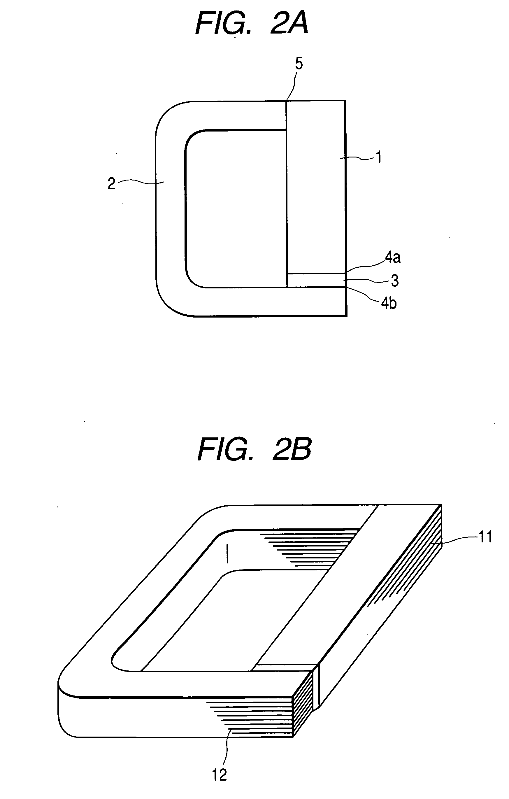
[0024] Then, Embodiment 3 will be described referring to FIG. 5. Usually, there is only a small difference in sectional area between the exciting core and the closed magnetic path forming core for the purpose of securing an area for the magnetic path. Accordingly, the sectional areas of the exciting core 11 and the closed magnetic path forming core 112 are close to each other as shown in FIG. 2B. However, provided that the closed magnetic path forming core 12 can obtain same magnetic density as that of the exciting core 11, the cores need not have the same sectional shape. Therefore, in case where a predetermined area is secured as the sectional area of the gaps, the sectional shapes of the iron cores can be optionally changed. In FIG. 5, as compared with the exciting core 31, the closed magnetic path forming cores (32, 36, 37) have an elongated shape. As the results, the faces to be contacted will be limited, and it would be necessary to control the flatness of only the faces to be...


PUM


Abstract

The ignition coil includes an exciting core having a substantially I-shape, and a closed magnetic path forming core having a substantially C-shape. The ignition coil is constructed in such a manner that first contact faces are formed by a first face of the exciting core and a first face of the closed magnetic path forming core, and a permanent magnet is arranged between these first contact faces, while second contact faces are formed by a second face of the exciting core which is directed to a different direction from the aforesaid first face and a second face of the closed magnetic path forming core which is directed to a different direction from the aforesaid first face.

Description

BACKGROUND OF THE INVENTION [0001] 1. Field of the Invention [0002] The present invention relates to an ignition coil which is used mainly in an internal combustion engine for a vehicle. [0003] 2. Description of the Related Art [0004] In an ignition coil having an iron core which is provided with a primary coil and a secondary coil wound therearound to form a closed magnetic path, and a permanent magnet which is provided in a part of the iron core, high electric voltage is generated in the secondary coil by supplying a primary current to the primary coil and thereafter cutting it off, thereby to actuate an ignition plug for igniting fuel of the internal combustion engine. Although performance of the ignition coil may depend on specifications of the primary and secondary coils for this purpose, the iron core, permanent magnet, and gaps between them which form the magnetic path have been also significant factors for influencing the performance of the ignition coil. Further, the gaps u...

Claims


Application Information

Patent Timeline
IPC IPC(8): H01F38/12F02P3/02
CPCH01F2038/127H01F38/12F02P3/02
Inventor MAEKAWA, TOSHIOMURATA, SHIGEMI
Owner MITSUBISHI ELECTRIC CORP
Features
  • Generate Ideas
  • Intellectual Property
  • Life Sciences
  • Materials
  • Tech Scout
  • Unparalleled Data Quality
  • Higher Quality Content
  • 60% Fewer Hallucinations
Learn More