
Cooling module of computer system and related apparatus with air wall for preventing recycling of heated air

Inactive Publication Date: 2005-06-23
WISTRON CORP
View PDF8 Cites 6 Cited by
  • Summary
  • Abstract
  • Description
  • Claims
  • Application Information

AI Technical Summary

Benefits of technology

[0008] It is therefore a primary objective of the claimed invention to provide a cooling module with an air wall, which prevents heated air provided by a heat sink module from flowing into an air inlet of a fan module of the cooling module, so as to increase heat dissipation efficiency of the heat sink module.
[0009] Briefly described, a cooling module of a computer system includes: a fan module, a heat sink module, and an air wall. The fan module having an air inlet and an air outlet is capable of drawing air into the air inlet and exhausting air from the air outlet. The heat sink module includes an air inlet, an air outlet, and a heat conduction part. The heat conduction part is between the air inlet and the air outlet and connects to a circuit of the computer system. The air inlet connects to the air outlet of the fan module. Moreover, the heat sink module is capable of drawing air into the air inlet and through the heat conduction part to exhaust air from the air outlet. The air wall is located between the air inlet of the fan module and the air outlet of the heat sink module for isolating airflow from the air outlet of the heat sink module to the air inlet of the fan module, so that heated air from the air outlet of the heat sink module is prevented from flowing into the air inlet of the fan module.

Problems solved by technology

Therefore, how to increase efficiency of heat dissipation in the computer system becomes one of the most important issues for development in modern information technology.

Method used


Image

  • Cooling module of computer system and related apparatus with air wall for preventing recycling of heated air
  • Cooling module of computer system and related apparatus with air wall for preventing recycling of heated air
  • Cooling module of computer system and related apparatus with air wall for preventing recycling of heated air

Examples


Embodiment Construction

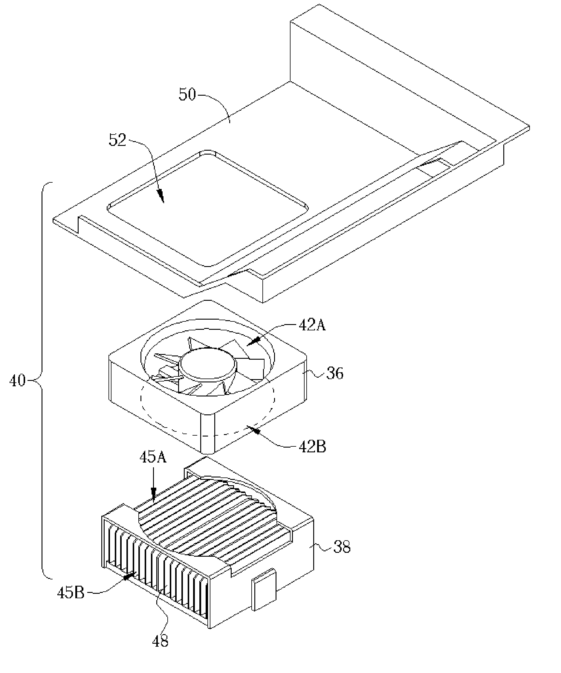
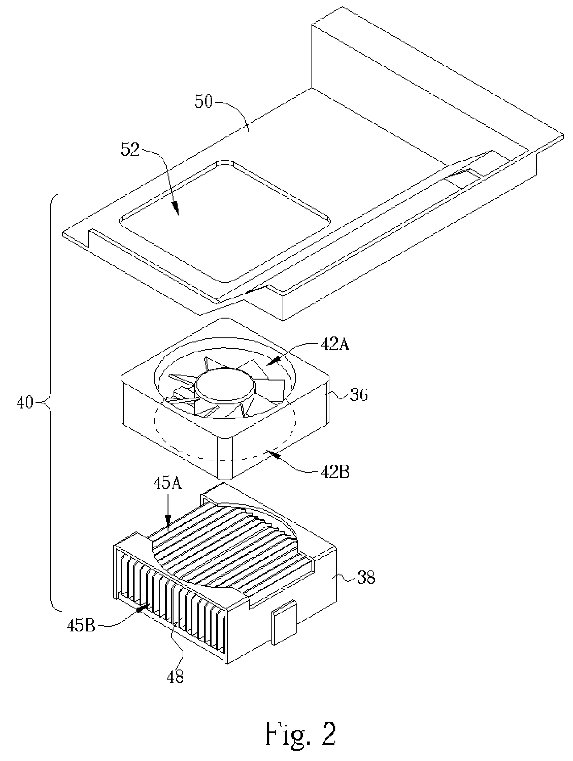
[0019] Please refer to FIG. 2, which illustrates a present invention cooling module 40. The cooling module 40 includes a fan module 36, a heat sink module 38, and an air wall 50. The fan module 36 includes an electric fan that draws air into an air inlet 42A and exhausts air from an air outlet 42B. The heat sink module 38 includes a plurality of radiator fins 48 for heat conduction; among the radiator fins 48 are an air inlet 45A and an air outlet 45B. The fan module 36 is disposed on the heat sink module 38 and blows air into the heat sink module 38 through the air inlet 45A to each radiator fin 48, heated air being exhausted from the air outlet 45B. The cooling module 40 further includes an air wall 50 for isolating airflow from the air outlet 45B to the air inlet 42A, so that air from the air outlet 45B is prevented from being recycled into the air inlet 42A. As shown in FIG. 2, the air wall 50 includes an approach 52, which matches the sizes of the air outlet 42B and the air inl...


PUM


Abstract

A cooling module for a computer system has a fan module, a heat sink module and an air wall. The heat sink module is connected to a circuit of the computer system for conducting heat generated by the circuit. The fan module makes air flow from an air inlet of the fan to the heat sink module where air absorbs heat generated by the circuit, and flow out from an air outlet of the heat sink module. The air wall is set between the air inlet of the fan and the air outlet of the heat sink module for isolating airflow from the air outlet of the heat sink module to the air inlet of the fan, such that heated air from the air outlet of the heat sink module will not significantly flow into the air inlet of the fan, and cooling efficient is therefore increased.

Description

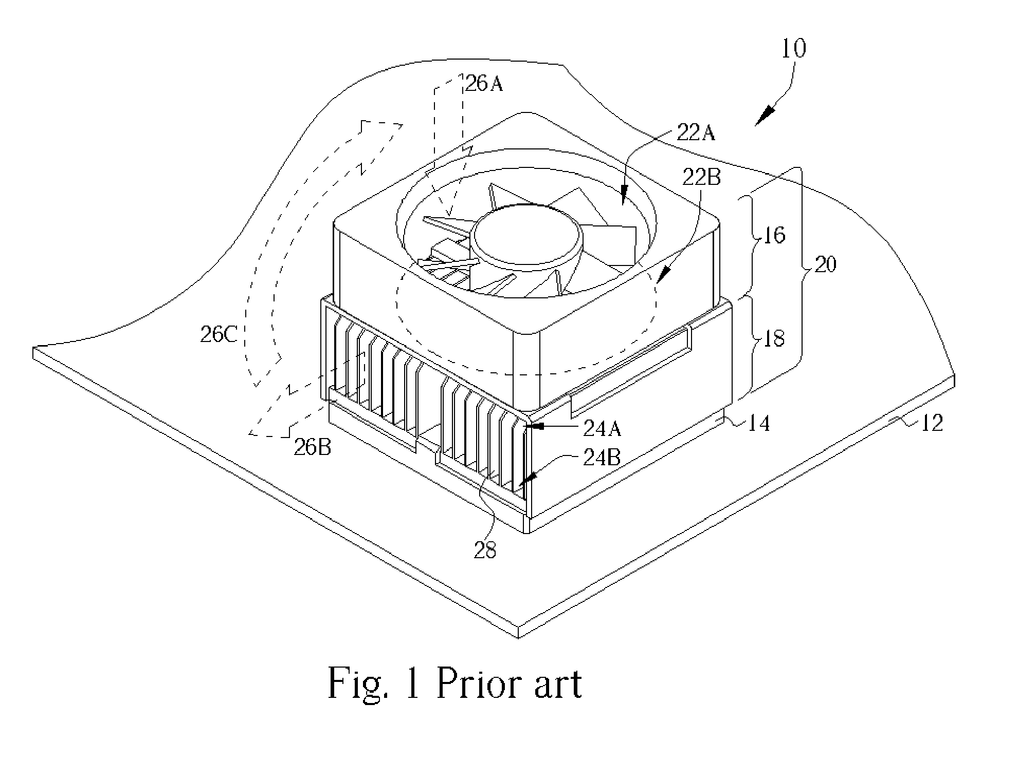
BACKGROUND OF INVENTION [0001] 1. Field of the Invention [0002] The present invention provides a cooling module of a computer system and related apparatus, and more particularly, a cooling module with an air wall preventing heated air from being recycled. [0003] 2. Description of the Prior Art [0004] Computers have become the most important information hardware of modern times. The higher the processing speed, the higher the temperature in a computer system (especially from heat generated by a central processing unit—CPU). Only if heat of the computer system can be effectively dissipated, can the computer system operate properly and stably. Therefore, how to increase efficiency of heat dissipation in the computer system becomes one of the most important issues for development in modern information technology. [0005] Please refer to FIG. 1, which illustrates a prior art air-cooled cooling module 20 of a computer system 10. Circuits of the computer system 10 are set in a motherboard 1...

Claims


Application Information

Patent Timeline
IPC IPC(8): G06F1/16G06F1/20H01L23/467H05K7/20
CPCG06F1/20H01L23/467H01L2924/0002H01L2924/00
Inventor CHIANG, HSIEN-CHINWANG, CHENG-PANG
Owner WISTRON CORP
Learn More