Photovoltaic module with ceramic coating heat radiating sheet

Inactive Publication Date: 2012-03-22
PARK CHUNG KWON +1
View PDF3 Cites 13 Cited by
  • Summary
  • Abstract
  • Description
  • Claims
  • Application Information

AI Technical Summary

Benefits of technology

[0018]The photovoltaic module of the present invention implements a structure in which a heat-dissipating sheet formed with a ceramic coating layer is attached thereto through an improvement of an existing photovoltaic module. The inventive photovoltaic module has advantageous effects in that the ceramic coating layer is formed on a side opposite to a side of the heat-dissipating sheet abutting against the back sheet, so that heat generated from a solar cell due to the differences in thermal emissivity, thermal shear rate and surface area of a material is transferred to a solar EVA film and then a heat-dissipating sheet thin plate serving as a carrier, and reaches the ceramic coating layer for emission, thereby resulting in an increase in heat dissipating efficiency. In addition, a high thermal emissivity is obtained by allowing a so-called heat transfer phenomenon to occur in one direction, which resultantly improves a heat dissipation performance and increases the cooling efficiency of the photovoltaic module and its peripheral devices to thus lo

Problems solved by technology

Generally, unlike the expectation that the efficiency of electricity generation from solar will also be the highest during the summer time when the solar irradiation is the highest, the photovoltaic module shows a substantially low electricity generation efficiency by the surface temperature thereof.
However, since a typical photovoltaic module has a structure of including a glass substrate 10, a front side solar EVE film 20, solar cells 30, a back side solar EVA film 40, and a back sheet 50 and employs an EVA polymeric material as shown in FIG. 3, the heat generated from the photovoltaic module itself and the low heat-dissipating effect of peripheral devices thereof are the greatest obstacle to the photovoltaic power generation.
However, the above photovoltaic module entails problems in that the cooling pipe 150 through which the cooling fluid flows is embedded in the photovoltaic module, so that the weight of the module is increased, which results in limited installation space of the module as well as complicated the structure of the module, thus making it difficult to manufacture the module.
In addition, the conventional photovoltaic module encounters a problem in that a separate place is requi

Method used


Image

  • Photovoltaic module with ceramic coating heat radiating sheet
  • Photovoltaic module with ceramic coating heat radiating sheet
  • Photovoltaic module with ceramic coating heat radiating sheet

Examples


Example

EXAMPLE 1

Manufacture of Attachable Type Module

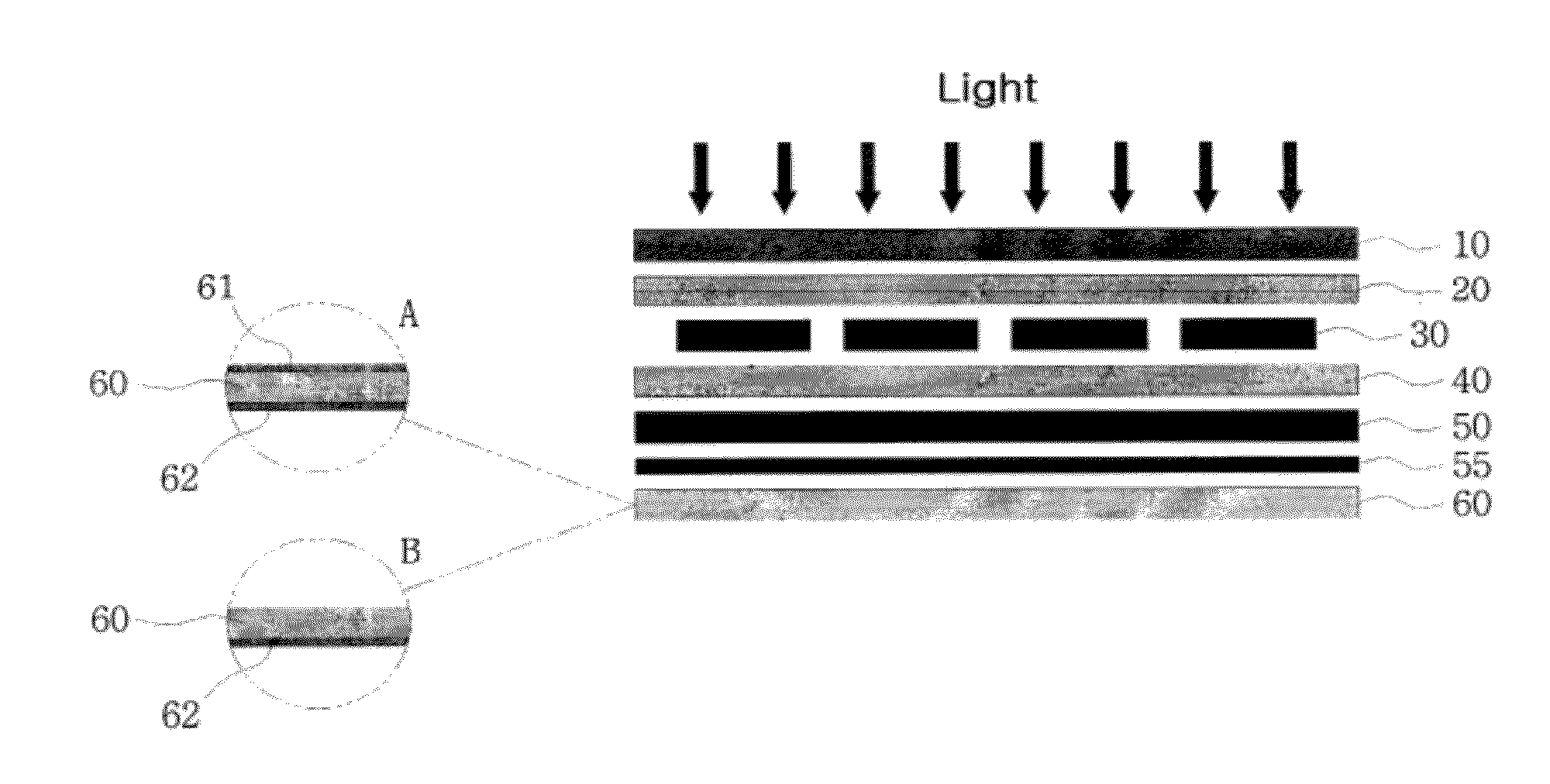
[0072]An attachable type module was manufactured in which the glass substrate 10, the front side solar EVA film 20, the solar cells 30, the back side solar EVA film 40, the back sheet 50, the pressure sensitive adhesive pressure-sensitive adhesive double-coated tape tape 55, and the heat-dissipating sheet 60 having the ceramic coating layer formed thereon are sequentially laminated in this order.

[0073]In addition, in the module according to Example 1, the thicknesses of the glass substrate 10, the front side solar EVA film 20, the solar cells 30, the back side solar EVA film 40, the back sheet 50, and the heat-dissipating sheet 60 were 2±0.1 mm, 1.5±0.1 mm, 0.2±0.05 mm, 1.5±0.1 mm, 0.3±0.1 mm, and 0.3±0.1 mm, respectively.

[0074]Besides, the heat-dissipating sheet used in the Example 1 is formed as an aluminum thin film, the material of the back sheet is fluorocarbon resin, the thicknesses of the ceramic coating layer formed on both sides...

Example

EXAMPLE 2

Manufacture of Replaceable Sheet Type Module

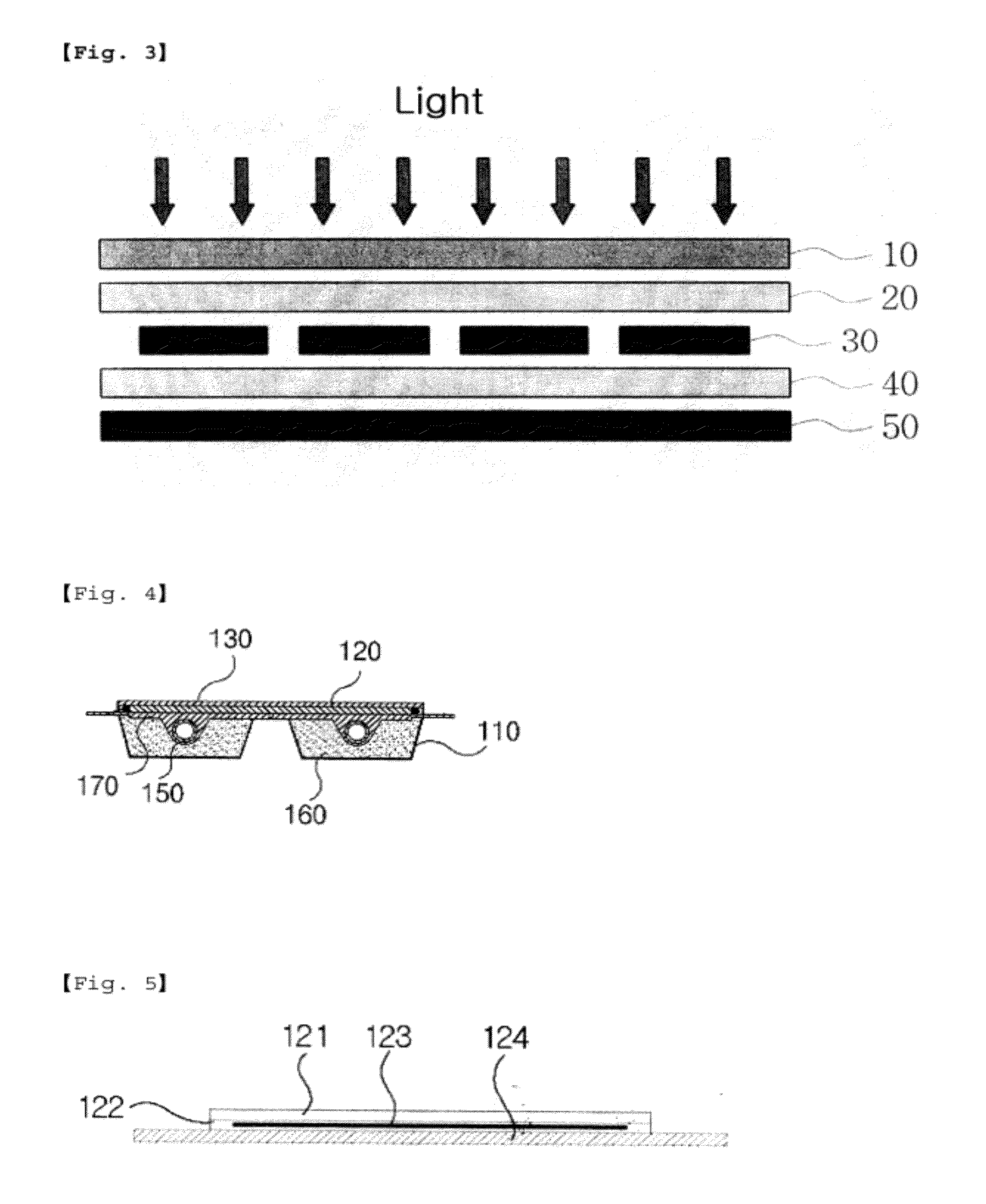
[0076]A replaceable sheet type module was manufactured in which the glass substrate 10, the front side solar EVA film 20, the solar cells 30, the back side solar EVA film 40, and the heat-dissipating sheet 60 having the ceramic coating layer formed thereon are sequentially laminated in this order.

[0077]Also, in the module according to the Example 2, the same conditions as those in the Example 1 were applied to the thicknesses of the glass substrate 10, the front side solar EVA film 20, the solar cell 30, the back side solar EVA film 40, and the heat-dissipating sheet 60.

[0078]In addition, the material of the heat-dissipating sheet and the back sheet used in Example 2 was the same as that in Example 1, and the same conditions as those in Example 1 were applied to the thicknesses and the kind of the ceramic coating layer formed on both sides of the heat-dissipating sheet.

Example

COMPARATIVE EXAMPLE 1

Manufacture of Existing Module

[0079]A conventional photovoltaic module was manufactured which includes the glass substrate 10, the front side solar EVA film 20, the solar cells 30, the back side solar EVA film 40, and the heat-dissipating sheet 60, and was used as a control group for comparison with the Examples 1 and 2.

[0080]In addition, the thicknesses of the respective laminated materials in the module of Comparative Example 1 applied the same conditions as those of the limited thicknesses in the above Example 1. The material of the heat-dissipating sheet used in this Comparative Example 1 used an aluminum thin film which is not formed with a ceramic coating layer.

[0081]3. Heat-Dissipating Sheet Materials and Heat-Dissipating Effect by Surface Treatment

[0082]The surface temperatures of the heat-dissipating sheets 60 of the modules, applied to Examples 1 and 2 using the measurement facility of the heat-dissipating effect of the photovoltaic module as construct...


PUM


Abstract

The present invention relates to a photovoltaic module characterized by comprising a heat radiating sheet overlaid with a ceramic coating layer, which is attached to a conventional photovoltaic module. In a method of increasing heat radiation with the aid of the ceramic coating layer provided on both sides or one side of the heat radiating sheet, heat generated by a solar cell due to the differences in thermal emissivity, thermal shear rate and surface area of a material is transferred to a solar EVA and then a heat radiating sheet thin plate that serves as a carrier, and returns back to the ceramic coating layer for emission. A high thermal emissivity is obtained by having a so-called heat transfer phenomenon in one direction, which resultantly improves a heat radiation performance and increases the refrigeration efficiency of the photovoltaic module and its peripheral devices to thus lower the internal temperature. As such, the power generation rate and efficiency through a module to which the heat radiating sheet is applied can be maximized, and a photovoltaic module with such a heat radiating sheet can maintain a change in the power generation rate traditionally due to a change in the surface temperature at a constant level, thereby increasing the annual power generation rate by 3-5% compared to that of the conventional one and improving the power generation effect during the summer season by 5-10%. Further, wide applicability can be ensured by equally applying the photovoltaic module of the present invention to areas having severe heat or high-temperature and high-humidity tropical weather as well as desert areas. In addition, the photovoltaic module according to the present invention is advantageous in that it is applicable not only to a new module but also to an already existing module, which makes it possible to manufacture those photovoltaic modules under the same process conditions as with the conventional ones without modifying the existing equipment.

Description

TECHNICAL FIELD[0001]The present invention relates to a photovoltaic module in which a heat-dissipating sheet having a ceramic coating layer formed thereon is attached to an existing photovoltaic module, and more particularly, to such a photovoltaic module in which the photovoltaic module and peripheral devices thereof is cooled by using the heat-dissipating properties improved by a ceramic coating layer formed on the outer surface of a heat-dissipating sheet, thereby maximizing the amount of electricity generated from solar and improving the durability of the photovoltaic module through the ceramic coating layer.BACKGROUND ART[0002]In general, it is known that photovoltaic power generation is relatively high in electricity generation efficiency in an area where solar irradiation is high. A photovoltaic power generation facility is currently being built in a photovoltaic power generation business area while being closely associated with the solar irradiation.[0003]In case of a typic...

Claims


Application Information

Patent Timeline
IPC IPC(8): H01L31/024H01L31/052
CPCY02E10/50H01L31/049H01L31/052H02S40/42
Inventor PARK, CHUNG KWONJANG, GYU HWAN
Owner PARK CHUNG KWON
Why Eureka
Try Eureka