Air-cooling heat dissipation device

Active Publication Date: 2018-08-23
MICROJET TECH
View PDF0 Cites 5 Cited by
  • Summary
  • Abstract
  • Description
  • Claims
  • Application Information

AI Technical Summary

Benefits of technology

[0007]An object of the present invention provides an air-cooling heat dissipation device. The air-cooling heat dissipation device is applied to an electronic device to remove heat from electronic components of the electronic device through lateral convection. The use of the air-cooling heat dissipation device can increase the heat dissip

Problems solved by technology

Generally, the limited space inside the electronic device is equipped with various high-integration or high-power electronic components for increasing the computing speed and the function of the electronic device, thus generating a great deal of heat during operations.
Consequently, the temperature inside the device is increased and high temperature is harmful to the components.
Since the electronic device is usually designed as possible as in slim, flat and succinct appearance, it has insufficient inner space for dissipating the waste heat.
In case that the heat is not effectively dissipated away, the electronic components of the electronic device are adversely affected by the heat and the high temperatu

Method used


Image

  • Air-cooling heat dissipation device
  • Air-cooling heat dissipation device
  • Air-cooling heat dissipation device

Examples


Embodiment Construction

[0025]The present invention will now be described more specifically with reference to the following embodiments. It is to be noted that the following descriptions of preferred embodiments of this invention are presented herein for purpose of illustration and description only. It is not intended to be exhaustive or to be limited to the precise form disclosed.

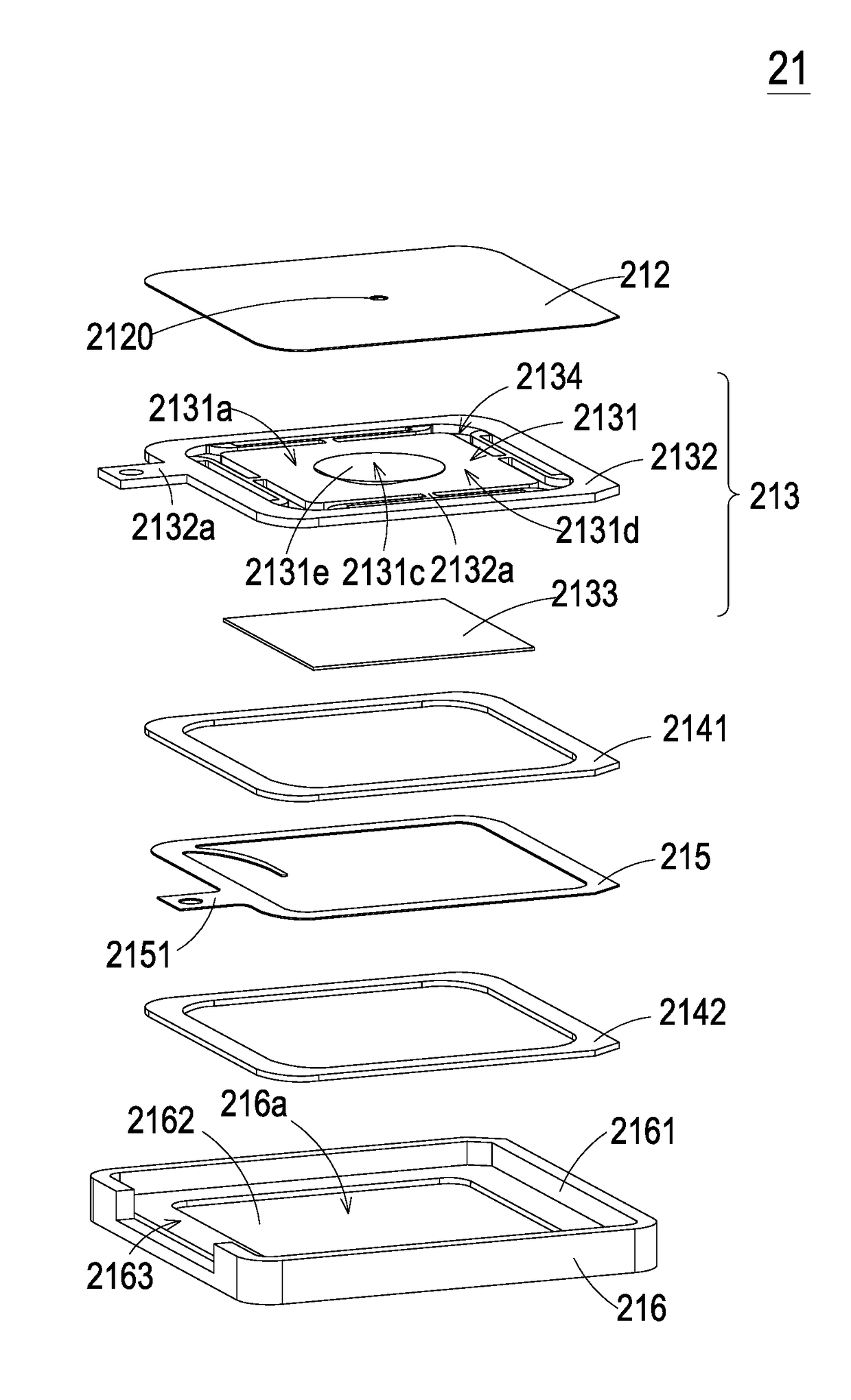
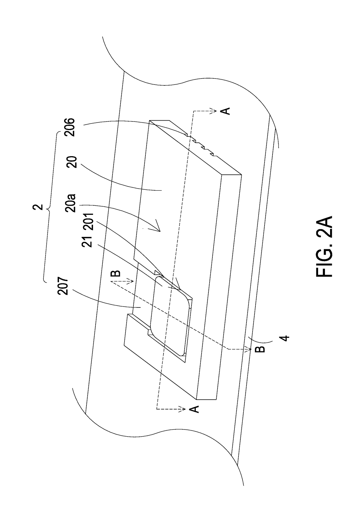
[0026]Please refer to FIGS. 2A, 2B, 3A and 3B. FIG. 2A is a schematic perspective view illustrating the structure of an air-cooling heat dissipation device according to an embodiment of the present invention. FIG. 2B is a schematic cross-sectional view illustrating the air-cooling heat dissipation device of FIG. 2A and taken along the line AA. FIG. 3A is a schematic perspective view illustrating a guiding carrier of the air-cooling heat dissipation device as shown in FIG. 2A, in which the gas pump is not shown. FIG. 3B is a schematic perspective view illustrating the guiding carrier of FIG. 2A and taken along the bottom side.

[002...


PUM


Abstract

An air-cooling heat dissipation device includes a guiding carrier and a gas pump. The guiding carrier includes a pump-receiving recess, a first guiding chamber, a second guiding chamber, a communication structure and at least one discharge groove. The first guiding chamber is concavely formed in the pump-receiving recess, and is in communication with the first guiding chamber. The communication structure is communicating between the first guiding chamber and the second guiding chamber, while the electronic component is disposed within the second guiding chamber. The gas pump is disposed within the pump-receiving recess. When the gas pump is enabled, an ambient gas is driven to sequentially flow through the first guiding chamber, the communication structure and the second guiding chamber to remove the heat from the electronic component. Since the discharge groove is communicating between the second guiding chamber and exterior surroundings, the heated gas is outputted from the discharge groove.

Description

FIELD OF THE INVENTION[0001]The present invention relates to an air-cooling heat dissipation device, and more particularly to an air-cooling heat dissipation device using a gas pump to drive gas to remove heat.BACKGROUND OF THE INVENTION[0002]With increasing development of science and technology, the trends of designing electronic devices such as portable computers, tablet computers, industrial computers, portable communication devices or video players are designed toward minimization, easy portability and high performance. Generally, the limited space inside the electronic device is equipped with various high-integration or high-power electronic components for increasing the computing speed and the function of the electronic device, thus generating a great deal of heat during operations. Consequently, the temperature inside the device is increased and high temperature is harmful to the components. Since the electronic device is usually designed as possible as in slim, flat and succ...

Claims


Application Information

Patent Timeline
IPC IPC(8): H01L23/467G06F1/20H05K7/20
CPCH01L23/467G06F1/206H05K7/20136G06F1/203H05K7/20127Y02D10/00
Inventor CHEN, SHIH-CHANGLIAO, JIA-YUCHEN, JHENG-WEIHUANG, CHI-FENGHAN, YUNG-LUNG
Owner MICROJET TECH
Why Eureka
Try Eureka