Liquid-cooling heat dissipation device

Active Publication Date: 2021-06-10
COOLER MASTER CO LTD
View PDF9 Cites 2 Cited by
  • Summary
  • Abstract
  • Description
  • Claims
  • Application Information

AI Technical Summary

Benefits of technology

[0007]According to the liquid-cooling heat dissipation devices as discussed above, the way of stacking the base plate, the thermally-conductive component, and the heat exchanger can reduce the

Problems solved by technology

In general, the internal space of the computer is very limited, and which often makes it difficult to accommodate the required expansion cards.
Also, the expansion cards produce heat during operation, and the heat may cause damage to its electronic component if the heat is not timely and effectively removed.
However, the heat sink, the hea

Method used


Image

  • Liquid-cooling heat dissipation device
  • Liquid-cooling heat dissipation device
  • Liquid-cooling heat dissipation device

Examples


first embodiment

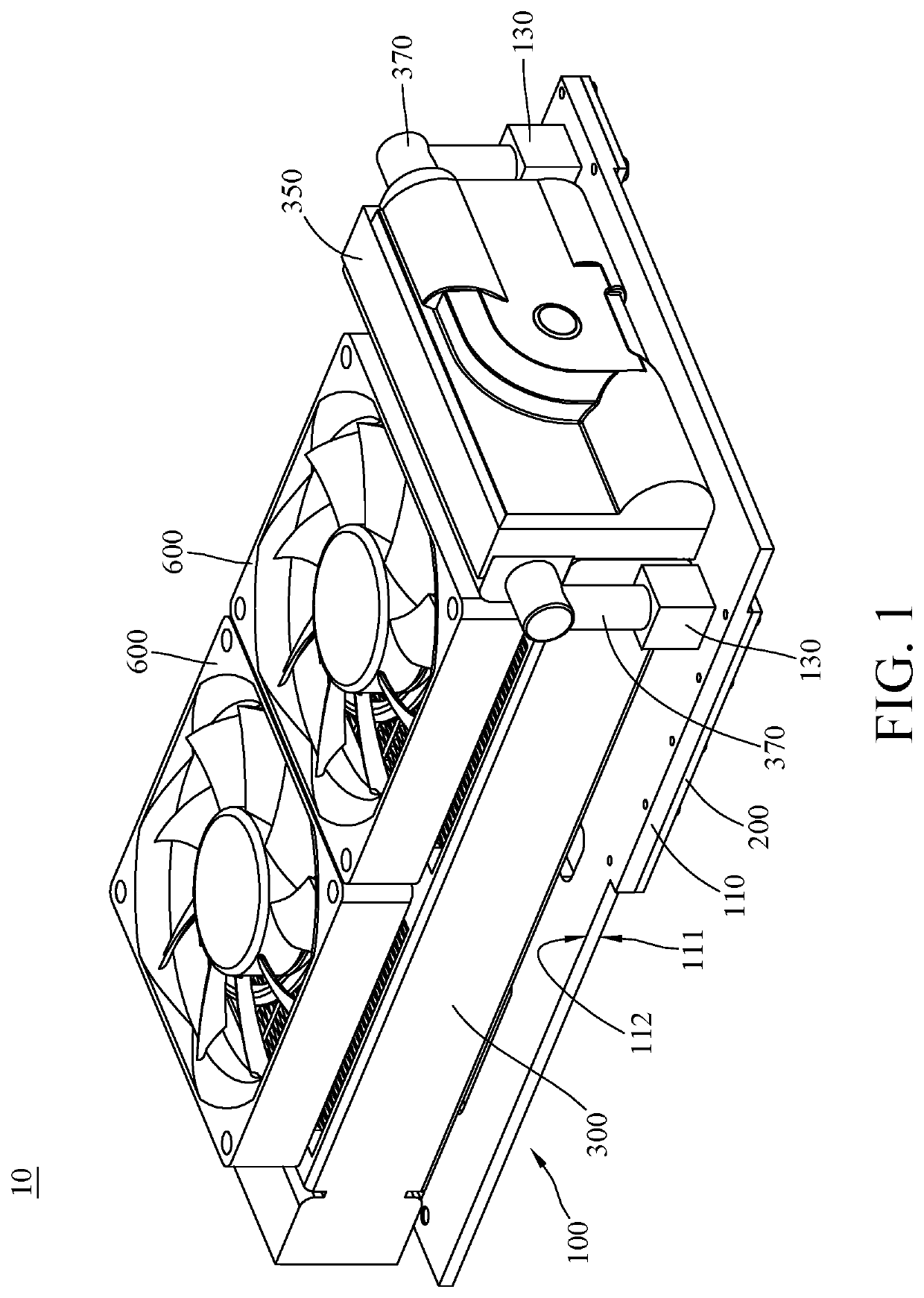
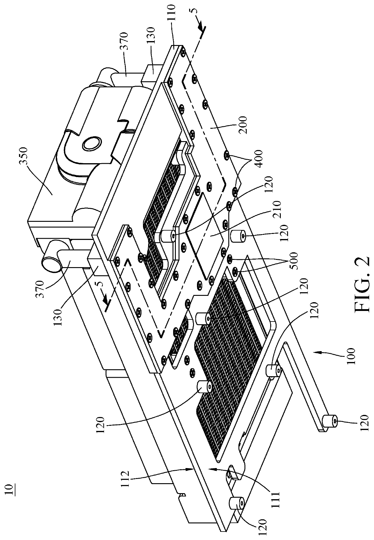
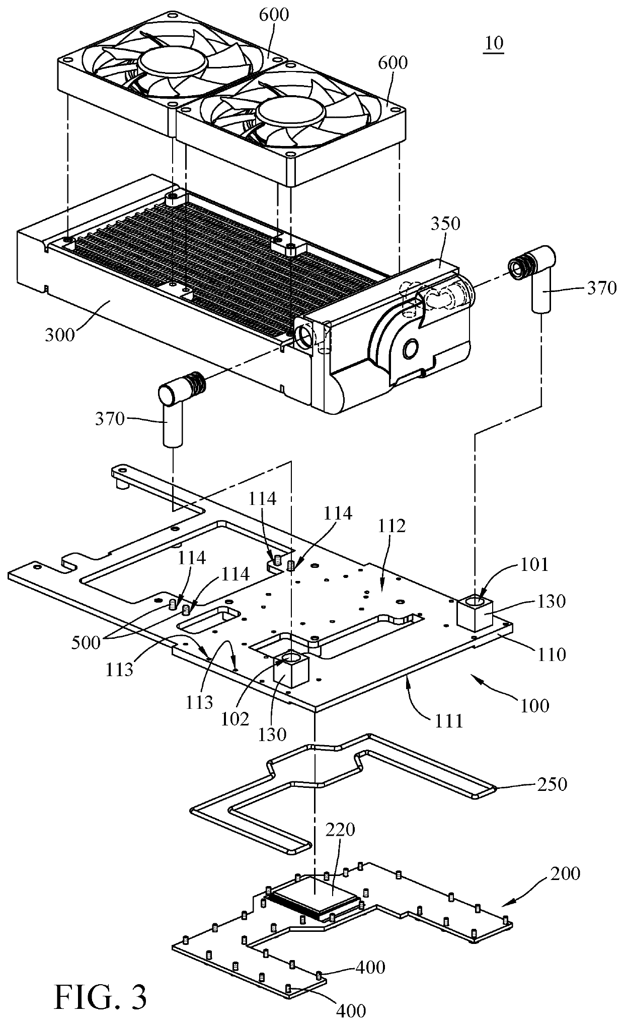
[0017]Referring to FIGS. 1 to 4, where FIG. 1 is a perspective view of a liquid-cooling heat dissipation device 10 according to the disclosure; FIG. 2 is another perspective view of the liquid-cooling heat dissipation device 10 in FIG. 1, FIG. 3 is an exploded view of the liquid-cooling heat dissipation device 10 in FIG. 1, and FIG. 4 is another exploded view of the liquid-cooling heat dissipation device 10 in FIG. 1.

[0018]In this embodiment, the liquid-cooling heat dissipation device 10 is configured to be in thermal contact with an expansion card (e.g., the expansion card 20 shown in FIG. 5). The expansion card 20 is, for example, a graphic card. The liquid-cooling heat dissipation device 10 includes a base plate 100, a thermally-conductive component 200 and a heat exchanger 300. In addition, the liquid-cooling heat dissipation device 10 further includes a plurality of first fasteners 400 and a plurality of second fasteners 500. The thermally-conductive component 200 is mounted on...

second embodiment

[0030]Referring to FIG. 6, where FIG. 6 is a side view of a liquid-cooling heat dissipation device 10′ according to the disclosure.

[0031]Note that one of the main differences between the liquid-cooling heat dissipation device 10′ and the liquid-cooling heat dissipation device 10 illustrated in the previous embodiment is the configuration of the pipes, thus only the differences will be specifically described below, and the same and similar parts may be briefly described or not be repeated.

[0032]In this embodiment, the liquid-cooling heat dissipation device 10′ is similar to the liquid-cooling heat dissipation device 10 but the rigid pipes 370 are replaced with two flexible pipes 370′. In such a case, the first liquid inlet 101 (shown in FIG. 5) and the first liquid outlet 102 (shown in FIG. 5) are respectively connected to the second liquid outlet 320 (shown in FIG. 5) and the second liquid inlet 310 (shown in FIG. 5) via the flexible pipes 370′.

[0033]According to the liquid-cooling ...


PUM


Abstract

The disclosure provides a liquid-cooling heat dissipation device. The liquid-cooling heat dissipation device is configured to be in thermal contact with an expansion card. The liquid-cooling heat dissipation device includes a base plate, a thermally-conductive component and a heat exchanger. The base plate is configured to be mounted on the expansion card. The thermally-conductive component is mounted on the base plate. The thermally-conductive component and the base plate together form a liquid chamber therebetween. The heat exchanger is mounted on the base plate and connected to the liquid chamber.

Description

CROSS-REFERENCE TO RELATED APPLICATIONS[0001]This non-provisional application claims priority under 35 U.S.C. § 119(a) on Patent Application No(s). 108216287 filed in R.O.C, Taiwan on Dec. 6, 2019, the entire contents of which are hereby incorporated by reference.TECHNICAL FIELD[0002]The disclosure relates to a heat dissipation device, more particularly to a liquid-cooling heat dissipation device.BACKGROUND[0003]As technology progresses and develops, computers are widely used and indispensable in daily life. In order to satisfy the various function requirements, the motherboard has expansion slots for adding expansion cards, such as graphic cards, sound card and / or network interface cards. In general, the internal space of the computer is very limited, and which often makes it difficult to accommodate the required expansion cards. Also, the expansion cards produce heat during operation, and the heat may cause damage to its electronic component if the heat is not timely and effective...

Claims


Application Information

Patent Timeline
IPC IPC(8): H05K7/20G06F1/20
CPCH05K7/20272H05K7/20254G06F2200/201H05K7/20172G06F1/20
Inventor SHIEH, TUNG-YANG
Owner COOLER MASTER CO LTD
Why Eureka
Try Eureka