Transformer/rectifier arrangement

Inactive Publication Date: 2006-06-13
E2V TECH (UK) LTD
View PDF21 Cites 2 Cited by
  • Summary
  • Abstract
  • Description
  • Claims
  • Application Information

AI Technical Summary

Benefits of technology

[0008]The arrangement of the present invention has the advantage that the rectifier diodes are arranged as an integral part of the secondary winding, thus reducing the space occupied by the transformer/rectifier. Furthermore, the secondary winding can be constructed on printed circuit boards disposed either side of the primary winding, connected by the rectifier d

Problems solved by technology

However, for example, in high voltage applications this rectified transformer arrangement can cause problems.
The rectifier diodes can have e

Method used


Image

  • Transformer/rectifier arrangement
  • Transformer/rectifier arrangement
  • Transformer/rectifier arrangement

Examples


Example

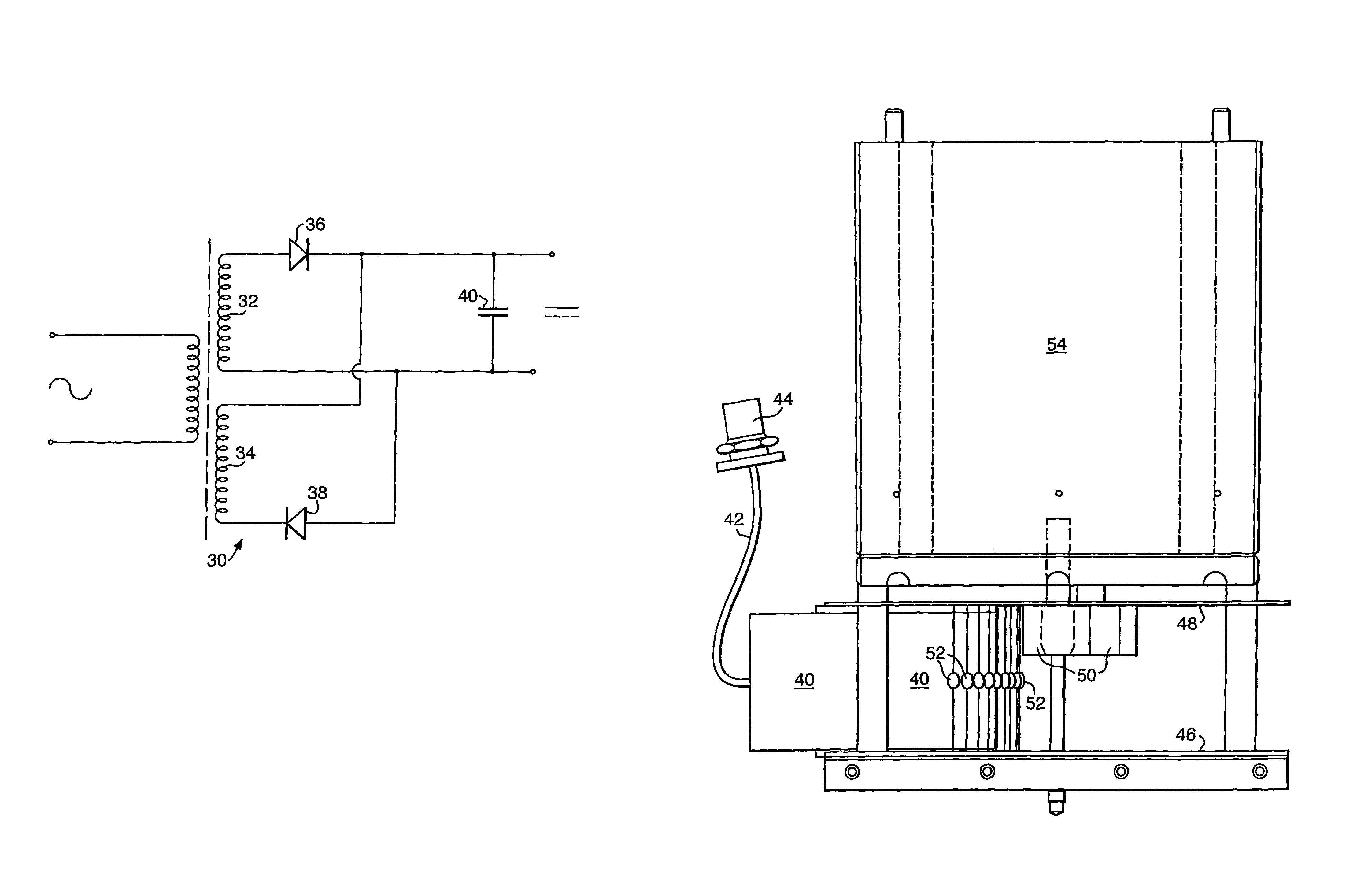
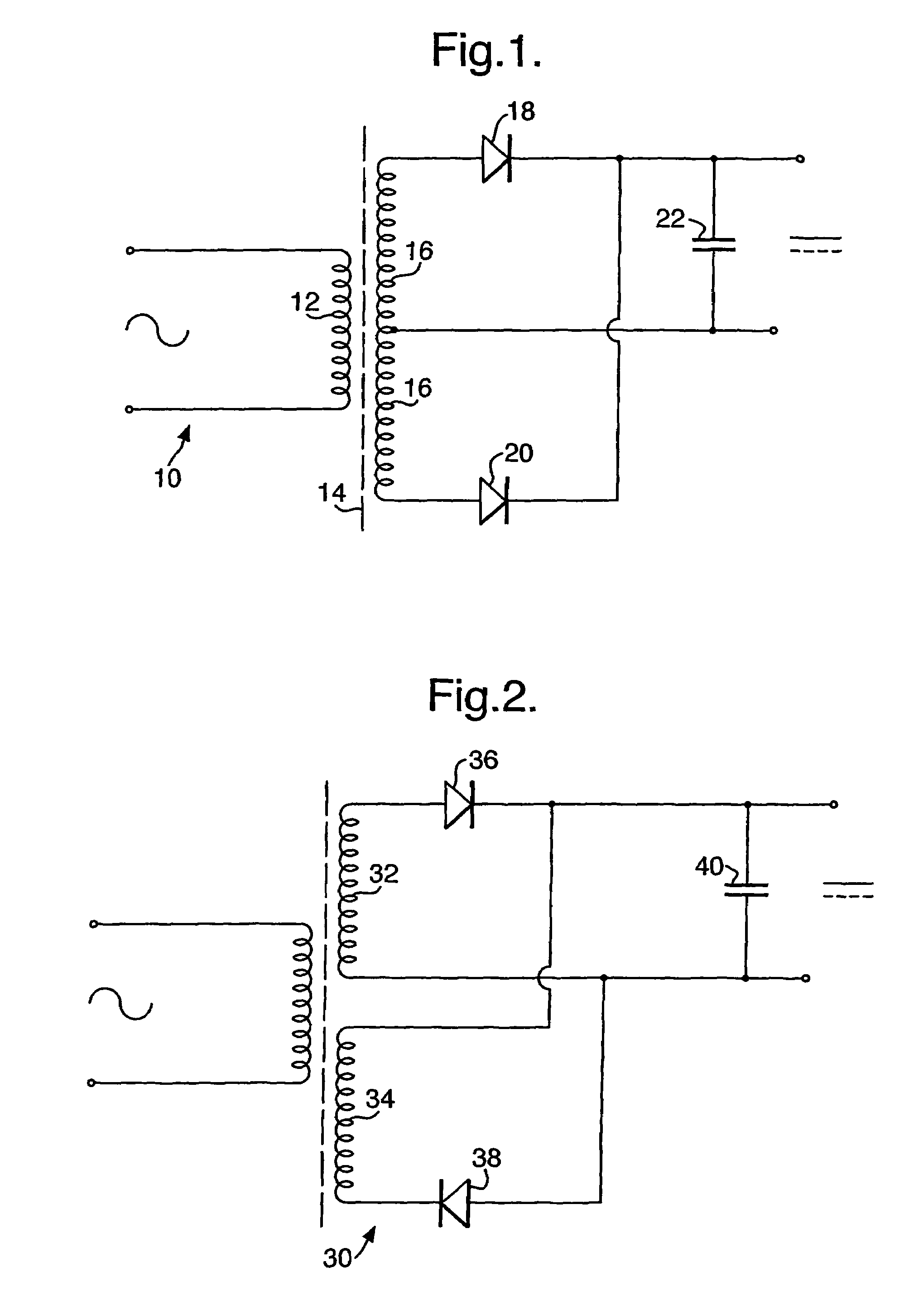
[0013]Referring to FIG. 2, a transformer / rectifier 30 arrangement is shown. The secondary coil is split into two discrete windings 32,34. Diodes 36,38 and capacitor 40 rectify the alternating voltage induced in the secondary coils to provide a steady DC voltage to the load, not shown. The circuit in FIG. 2 behaves in the same manner as that shown in FIG. 1, however there are important advantages of the circuit shown in FIG. 2 that are not present in prior art devices.

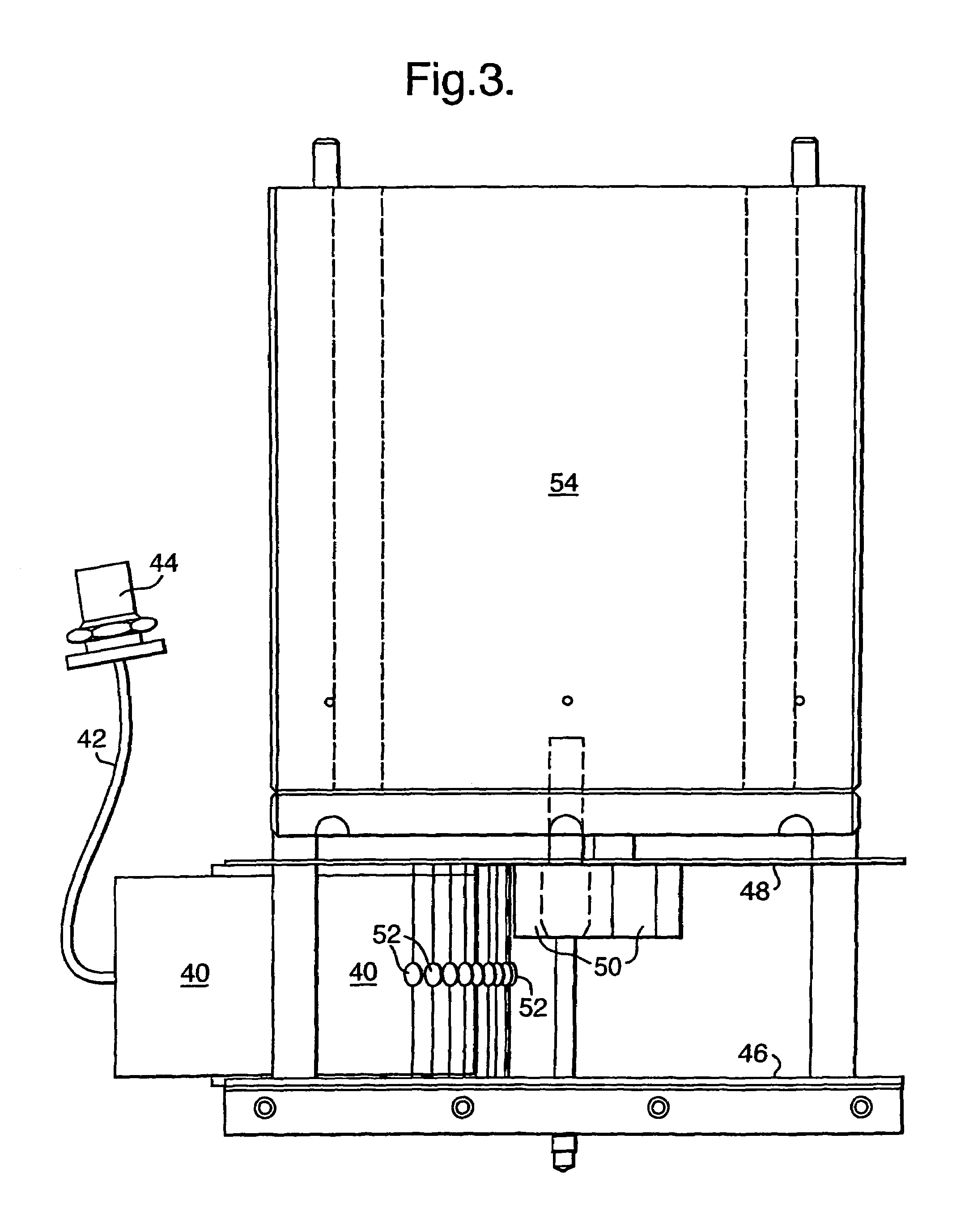
[0014]Referring to FIG. 3, a transformer primary coil and transformer core are housed in a cylindrical insulating plastic housing 40. Voltage is supplied to the primary coil by a cable 42 and cable socket 44. Printed circuit boards 46,48 are disposed on either side of the primary coil housing 40. Electronic components 50 are disposed on circuit board 48 and include a capacitor as part of a rectifier circuit. The rectifier circuit is completed by diodes 52 disposed between the circuit boards 46,48. The diodes are arrange...


PUM


Abstract

A rectifier transformer comprises two secondary windings, preferably with a single turn on each winding. The rectifier diodes form an integral part of each of the secondary windings. Thus, a compact arrangement is realised. In a high voltage application, the rectifier diodes comprise a plurality of relatively low voltage diodes in parallel to one another. The overall capacitance of the rectifier circuit is reduced by this arrangement.

Description

CROSS-REFERENCE TO RELATED APPLICATION[0001]This is a continuation of International Patent Application No. PCT / GB02 / 02733 filed Jun. 14, 2002, designating the United States and claiming priority of British Patent Application No. 0114678.6 filed Jun. 15, 2001, the disclosures of both foregoing applications being incorporated herein by reference.BACKGROUND OF THE INVENTION[0002]The present invention relates to electrical transformer / rectifier arrangements.[0003]Transformers are well known in the art for transforming electrical energy at an alternating voltage into electrical energy at another usually different alternating voltage without change of frequency. Transformers depend upon mutual induction and essentially consist of two electrical circuits magnetically coupled together. The usual construction comprises two coils or windings with a magnetic core disposed between them. The primary circuit receives energy from an AC supply whilst the secondary circuit delivers energy to a load,...

Claims


Application Information

Patent Timeline
IPC IPC(8): H01F5/00H02M3/00H02M1/00H01F27/28H01F27/40H01F30/04
CPCH01F27/2804H01F30/04H01F27/40
Inventor RICHARDSON, ROBERTISKANDER, STEPHEN MARKHICKS, MATTHEW KEVIN
Owner E2V TECH (UK) LTD
Why Eureka
Try Eureka