Image forming apparatus and image formation control method in the same

a technology of image forming apparatus and control method, which is applied in the direction of electrographic process apparatus, printing, instruments, etc., can solve the problems of inability to meet the high desired value, inability to perform printing operation, fluctuation of image reproducibility, etc., and achieve the effect of reducing the time for calibration

Active Publication Date: 2005-06-23
CANON KK
View PDF9 Cites 22 Cited by
  • Summary
  • Abstract
  • Description
  • Claims
  • Application Information

AI Technical Summary

Benefits of technology

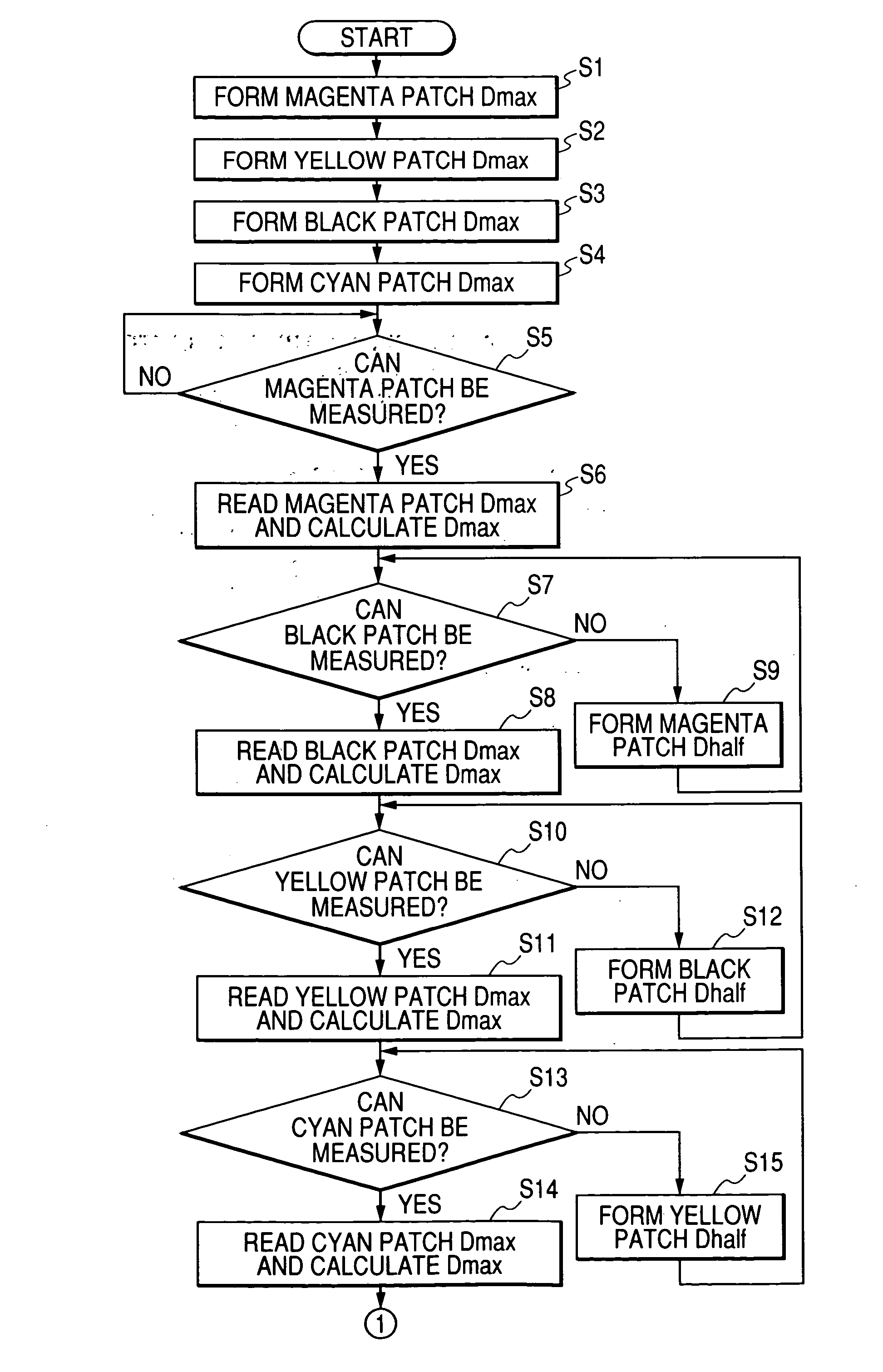
[0011] A still further object of the present invention is to provide an image forming control method in an image forming apparatus, comprising the steps described below. Specifically, it is an image forming control method in an image forming apparatus having a plurality of image forming parts and forming an image on a moving medium continuously moving on the plurality of image forming parts according to an arrangement order of the plurality of image forming parts, comprising the steps of: forming the first test image on the moving medium by using the plurality of image forming parts in the first order; measuring a density of the test image formed on the moving medium in the first test image forming step; setting the first image forming condition in a corresponding image forming part based on a result of measuring the density of the first test image in the density measuring step; forming the second test image on the moving medium by using the corresponding image forming part based on the first image forming condition in the second order; setting the second image forming condition in each of the plurality of image forming parts based on a result of measuring the density of the second test image; and controlling image forming processing in the plurality of image forming parts according to the first and second image forming conditions, wherein the first test image and the second test image are formed within specific dimensions by applying different orders to the first and second orders. According to the present invention, there is an effect of forming an image under optimum image forming conditions with a reduction of time for calibration.

Problems solved by technology

In an electrophotographic image forming apparatus such as a laser beam printer, however, image reproducibility fluctuates due to a change in environmental condition where the apparatus is placed or deterioration with time of a photosensitive member or developer.
Therefore, it cannot satisfy the high desired values over the long term if there is no change in the initialization.
A normal printing operation cannot be performed during the above calibration, thus the user have to wait for the finishing the calibration to execute the printing operation.

Method used


Image

  • Image forming apparatus and image formation control method in the same
  • Image forming apparatus and image formation control method in the same
  • Image forming apparatus and image formation control method in the same

Examples


first embodiment

[0070] Referring to FIG. 7, there is shown a sequence diagram for explaining patch formation and density measurement processing in an image forming apparatus according to the first embodiment of the present invention. In this regard, belt cleaning, base detection, and other processing are omitted, and mainly the characterizing parts of this embodiment such as timings and orders of the Dmax patch group formation and those of the Dhalf patch group formation will be described here. To simplify the description, it is assumed that there are settings of time “0” for changing the developing bias, CPU 110 processing time “0” for the Dmax calculation, and time “0” from a start of the image formation to an arrival of an electrostatic latent image at the developing part. Practically, these values cannot be “0” and differences in timing occur in the timing diagram. In relative comparisons with comparative examples described later, however, they do not damage effects of the present invention. Th...

second embodiment

[0103] The following describes an embodiment in which the patch group total length can be shorter than that of the comparative example 1 when using color orders other than those of the first embodiment.

[0104] Referring to FIGS. 12A, 12B, 12C and 12D, there is shown a diagram for explaining the color orders according to the second embodiment.

[0105] In FIGS. 12A, 12B, 12C and 12D, “Dmax station order” represents a station order in forming the Dmax patch groups. For example, representation “1234” indicates that the Dmax patch groups are formed on the ETB 20 in the order of the first station (Y), the second station (M), the third station (C), and the fourth station (K). Similarly, “Dhalf station order” represents a station order in forming the Dhalf patch groups. “Dmax color order” and “Dhalf color order” represent the order of the Dmax control and the order of the Dhalf control in an image forming apparatus according to this embodiment by means of colors: the station order “1234” cor...


PUM


Abstract

An image forming apparatus includes a plurality of image forming parts, a moving medium continuously moving on the image forming parts, first and second image forming devices, a test image density measuring device, and a control device. The first test image forming device forms a first test image on the medium by using the image forming parts in a first order. The second test image forming device forms a second test image on the medium. The control device controls image forming processing in the image forming parts based on a result of a density measurement of the second test image.

Description

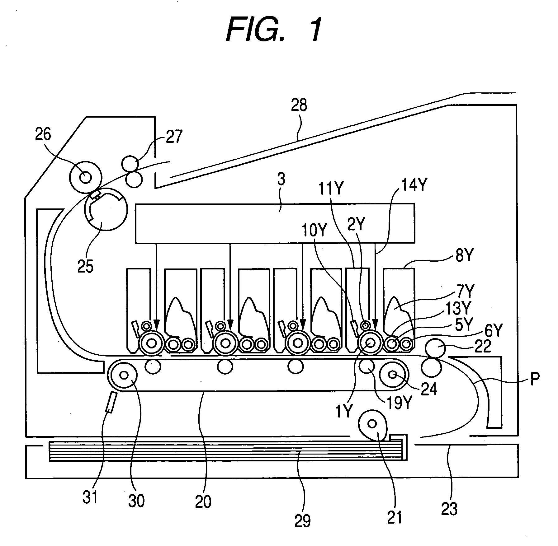
BACKGROUND OF THE INVENTION [0001] 1. Field of the Invention [0002] The present invention relates to an image forming apparatus such as, for example, a printer or a copying machine, and more particularly to an image forming apparatus having an arrangement of a plurality of image forming parts and an image formation control method in the same. [0003] 2. Related Background Art [0004] In recent years, a printer as an image output terminal has rapidly become popular. Particularly, with an advance of colorization, there are increasing demands for improving stability of printed image qualities in a color printer and for equalization of color image qualities among color printers. Particularly, color reproducibility on a printed image is required to have advanced stability of image reproduction independent of a change in the installation environment, a change with time, and a difference in printer type. In an electrophotographic image forming apparatus such as a laser beam printer, however,...

Claims


Application Information

Patent Timeline
Patent Type & Authority Applications(United States)
IPC IPC(8): B41J2/52B41J2/525G03G15/00G03G15/01G03G21/00H04N1/29
CPCG03G2215/0119G03G15/5062
Inventor NAKAGAWA, KEN
Owner CANON KK
Why Eureka
Try Eureka