Electronic fence system and controlling method thereof

a technology of electronic fence system and control method, applied in pasturing equipment, taming and training devices, instruments, etc., can solve the problems of fence requiring installation cost, fence creating an ill appearance, running away and returning to the wild, etc., and achieve the effect of preventing an arbitrary operation of the power switch

Active Publication Date: 2005-06-30
SOS
View PDF14 Cites 32 Cited by
  • Summary
  • Abstract
  • Description
  • Claims
  • Application Information

AI Technical Summary

Benefits of technology

[0024] Another objective of the present invention is to produce an electronic fence system and a controlling method thereof in which a power source can be applied to the receiver so that it is only activated when the power switch is pressed for a predetermined length of time, thus preventing an arbitrary operation of the power switch by an external object.

Problems solved by technology

Thus, if pets are not chained up or a fence for confining pets is not established, they can run away and return to the wild or wander about out of the owner's control.
There are problems, however, in that a fence requires an installation cost, and the fence creates an ill appearance.
Further, the fence can be spoiled owing to external forces like wind or rain, and a gap through which pets can pass may be formed.
The fence then, requires constant management and maintenance, as well as management personnel and its accompanying cost.
A receiver attached to the pet generates a shock to the pet when it approaches the wire within a certain range.
If a pet goes far away from the antenna, out of a predetermined range, a radio signal is no longer received and a receiver attached to the pet generates an electrical shock to the pet so that it may not escape from the designated area.
The conventional confinement system using a fence or a radio has problems in that since the sound signal is used as the warning, the pet cannot recognize the warning if the pet has hearing loss or the pet is in a noisy circumference.
It has a further problem in that an electric shock is directly given when moving out of the safe area, thus enabling the pet to get an excessive shock.

Method used


Image

  • Electronic fence system and controlling method thereof
  • Electronic fence system and controlling method thereof
  • Electronic fence system and controlling method thereof

Examples


Embodiment Construction

[0049] Reference should now be made to the drawings. The same reference numerals are used throughout the different drawings to designate components that are the same or similar.

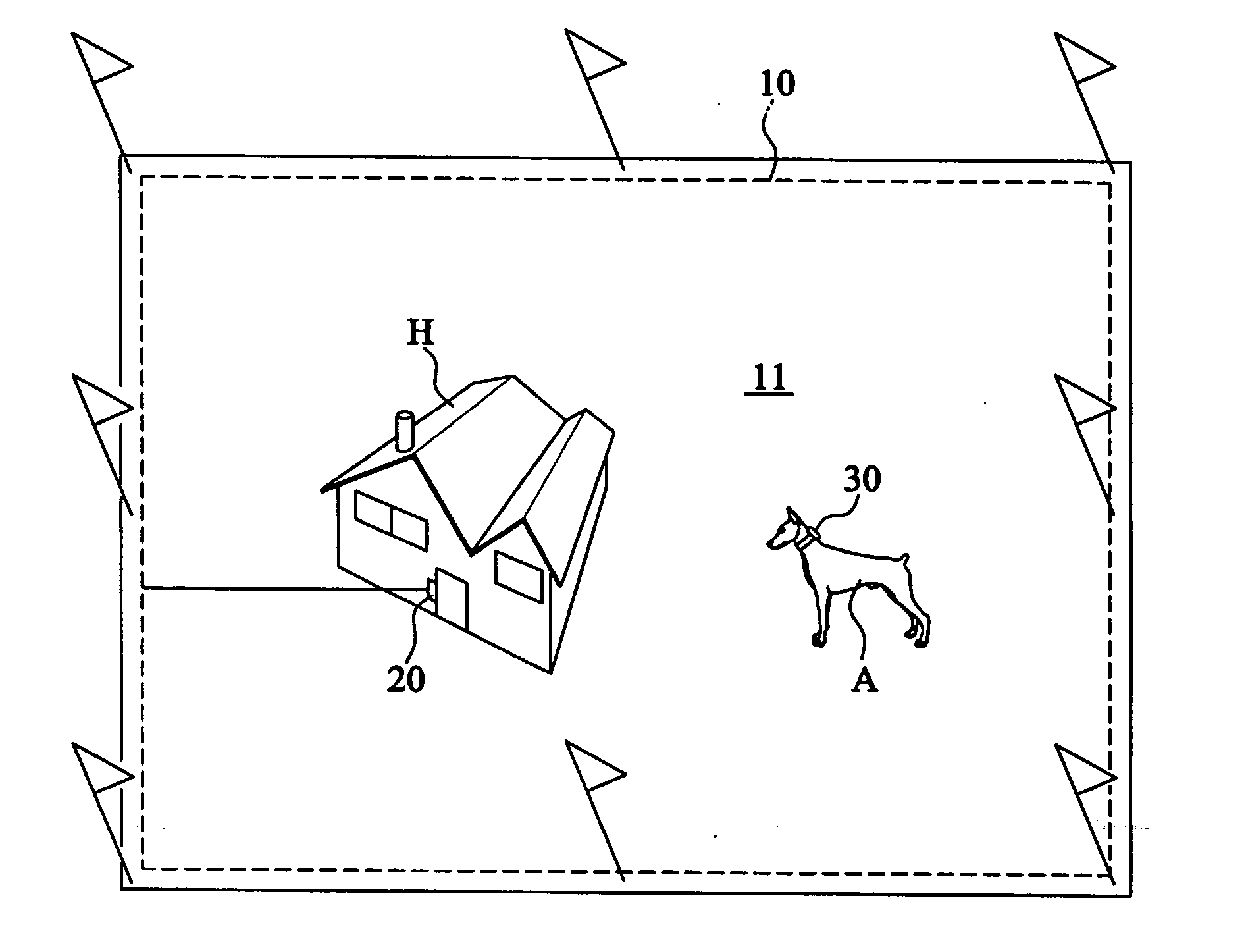
[0050]FIG. 3 is a view of an electronic system adopting a fence wire method according to the present invention.

[0051] An electronic fence system consists of a fence wire 10, which radiates a wireless signal for defining the boundary and is buried in the yard along the boundary of a confined area 11 within which a pet A may move about freely; a transmitter 20 electrically connected to the fence wire 10 and transmitting a boundary wireless signal for defining the boundary 11 to the fence wire 10, the boundary wireless signal includes a direct shock mode to the pet or a combination shock mode after first producing a sound; and a receiver 30 attached to the pet A which receives the boundary defining signal in respect to the pet's approach to the fence wire, and, depending on the selection mode, generates either...


PUM


Abstract

An electronic fence system comprises a fence wire which radiates a radio signal for defining a boundary; a transmitter electrically connected to the fence wire and transmitting a boundary radio signal including a mode selection signal; and a receiver attached to the pet, that receives the boundary defining signal, and that generates either electrical shock only, or a combination of electrical shock and vibration, or electrical shock and vibration as well as sound depending on the mode selection signal. If the pet has a hearing loss, or the circumference is noisy, a warning signal can be given through a touch to the skin of the pet. Since a vibration is applied first, and the shock follows it, no severe shock need be applied to the pet that will return into the confined area after having received a vibration. A pet's activity is restricted in a predetermined area.

Description

BACKGROUND OF THE INVENTION [0001] 1. Field of the Invention [0002] The present invention relates to an electronic fence system and controlling method and, more specifically, to a system and method in which a pet's activity in a predetermined area is restricted when the pet approaches a confined area. A boundary display signal is produced from the fence wire or a radio boundary display signal is sent to a receiver worn on the pet. The receiver gives a vibration (or vibration accompanied by sound) followed by an electric shock or a shock only to the pet. Therefore, the pet cannot move out of the confined area. [0003] 2. Description of the Prior Art [0004] Domestic animals are naturally wild. Thus, if pets are not chained up or a fence for confining pets is not established, they can run away and return to the wild or wander about out of the owner's control. [0005] Most people reserve space (e.g. yard etc.) in which their pet can run freely, and the space is enclosed with a fence inclu...

Claims


Application Information

Patent Timeline
Patent Type & Authority Applications(United States)
IPC IPC(8): A01K15/02A01K3/00
CPCA01K15/023A01K3/00A01K15/04H04W4/021
Inventor SO, HO YUN
Owner SOS
Why Eureka
Try Eureka