Eureka AIR delivers breakthrough ideas for toughest innovation challenges, trusted by R&D personnel around the world.

Thermoelectricity generator

a generator and thermal energy technology, applied in the direction of thermoelectric devices with peltier/seeback effect, basic electric elements, electric apparatus, etc., can solve the problems of unfulfilled efficiency and heat loss in the system, and achieve the effect of improving energy conversion devices and low conversion efficiency

Inactive Publication Date: 2005-06-30
STRNAD RICHARD J
View PDF1 Cites 37 Cited by
  • Summary
  • Abstract
  • Description
  • Claims
  • Application Information

AI Technical Summary

Benefits of technology

[0009] In view of the forgoing problems and mainly low conversion efficiency, the present invention has been devised, and it is an object of the present invention to provide a structure and method for improving energy conversion device.
[0010] In order to enhance the converting efficiency of the thermoelectric device, there are provided, according to one aspect of the invention, uneven current densities at both ends of connecting electrodes that includes in the example a circular structure.
[0011] Another object of the present invention is to design a thermoelectric device improved in mechanical ruggedness and simplicity helpful in assembly automation.
[0012] Still another object of the present invention is to provide a process according to which thermoelectric devices of the kind as described above can be manufactured with high yield and low manufacturing cost.
[0015] In the second aspect of the present invention, a thermoelectric battery, comprises: a plurality of thermoelectric device cells arranged and connected in series in order to increase the operating voltage for simplified utilization.

Problems solved by technology

It should be emphasized that, in actual device applications, there are other heat losses in the system and the efficiency is never fully realized.

Method used


Image

  • Thermoelectricity generator
  • Thermoelectricity generator
  • Thermoelectricity generator

Examples


Embodiment Construction

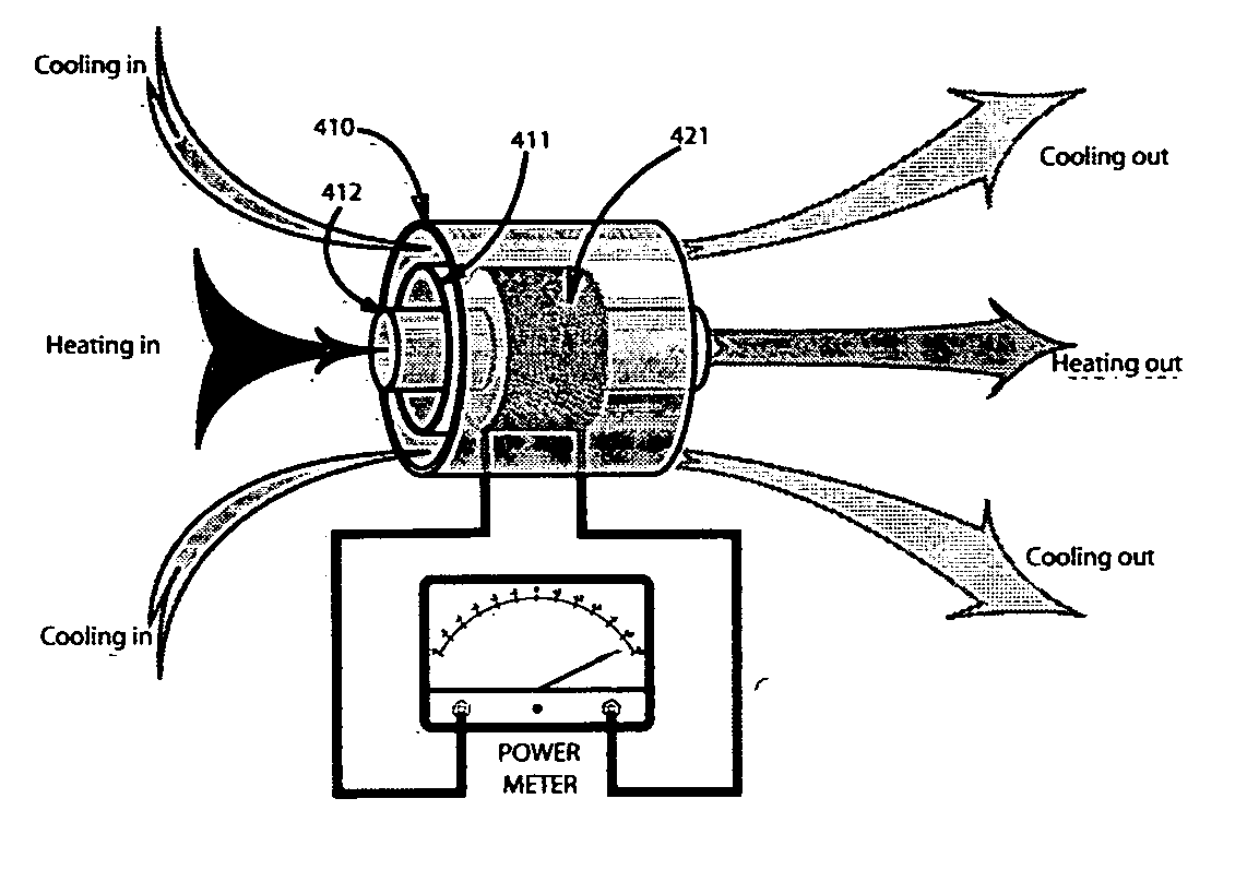
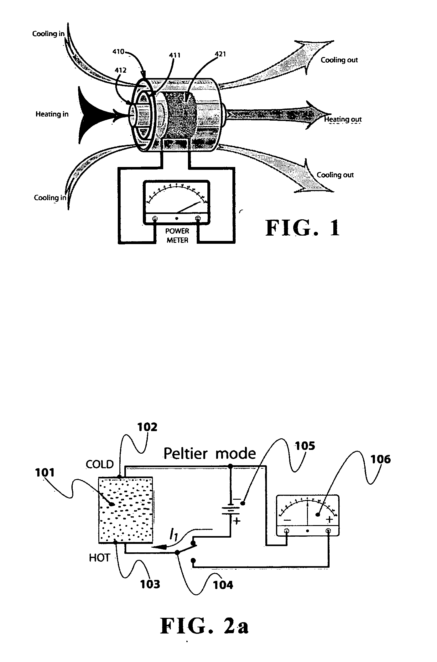
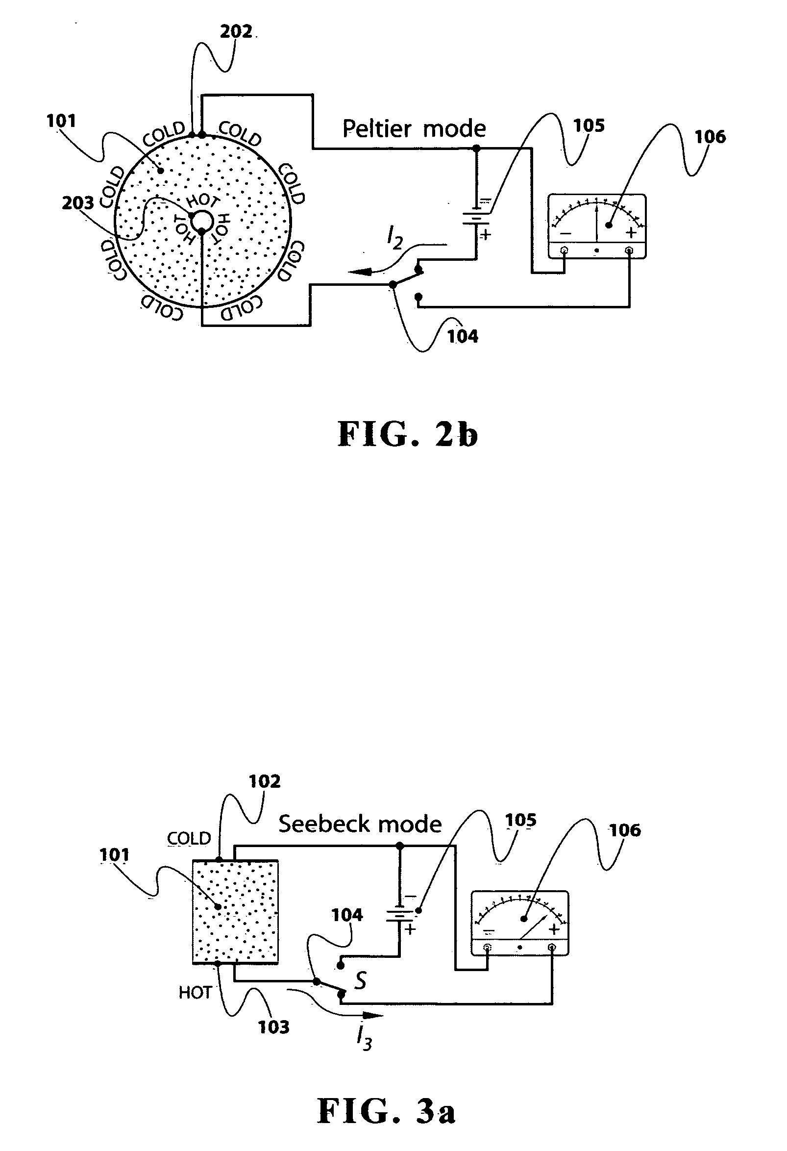
[0034] In the following detailed description of the preferred embodiments, reference is made to the accompanying drawings which form a part hereof, and in which is shown by way of illustration specific preferred embodiments in which the invention may be practiced. These embodiments are described in sufficient detail to enable those skilled in the art to practice the invention, and it is to be understood that other embodiments may be utilized and that logical, mechanical and electrical changes may be made without departing from the spirit or scope of the invention. To avoid detail not necessary to enable those skilled in the art to practice the invention, the description may omit certain information known to those skilled in the art. The following detailed descriptions, therefore, not to be taken in a limiting sense, and the scope of the present invention is defined only by the appended claims.

[0035] The conceptual ground work for the present invention involves fabricating a heat to...


PUM


Abstract

A non-linear, high efficiency thermoelectricity generator assembly contains disk shaped thermoelectric cells electrically connected in series to each other. The assembly may be used as a generator of electricity or as a cooling apparatus. In the electricity generating mode an external heat source is required. In the cooling mode, a power source is required to provide the necessary electrical energy.

Description

BACKGROUND OF THE INVENTION [0001] 1. Field of the Invention [0002] The present invention relates to a thermoelectricity generator and more particularly to an improved thermoelectricity generator that performs the conversion between thermal energy and electrical energy, and a method of fabricating the thermoelectric component of the generator. Further, the present invention relates to a thermoelectricity generator assembly which is fabricated by employing such thermoelectric components. [0003] 2. Description of the Related Art [0004] A thermoelectric generator converts heat into electrical energy. The conversion in a single junction involves generating low voltages and high currents. [0005] Thermoelectric voltage generation from the thermal gradient, present across the conductor, is inseparably connected to the generation of thermal gradient from applied electric current to the conductor. This interconversion of heat and electrical energy for power generation or heat pumping is base...

Claims


Application Information

Patent Timeline
Patent Type & Authority Applications(United States)
IPC IPC(8): H10N10/10H10N10/13H10N10/17
CPCH01L35/32H01L35/30H10N10/13H10N10/17
Inventor STRNAD, RICHARD J.
Owner STRNAD RICHARD J
Why Eureka
Eureka Blog
Learn More