Sensor for detection of the orientation of a magnetic field

a magnetic field and orientation sensor technology, applied in the direction of galvano-magnetic devices, magnetic field measurement using galvano-magnetic devices, instruments, etc., can solve the problems of disadvantageous subsequent signal processing, only showing a rather low output signal, and not being able to detect the direction of an externally applied magnetic field by means of a gmr-multilayer system

Inactive Publication Date: 2005-06-30
IBM CORP
View PDF5 Cites 39 Cited by
  • Summary
  • Abstract
  • Description
  • Claims
  • Application Information

AI Technical Summary

Benefits of technology

[0045] The present invention therefore provides a magnetic sensor and a magnetic sensor device as well as a signal processing system for the determination of the direction of a magnetic field. Preferably the source of the magnetic field is attached to a rotatable element and the direction of the magnetic field rotates with the angular movement of the rotatable element. Since the sensor determines the direction of the magnetic field,...

Problems solved by technology

Even though magnetic field sensors based on AMR materials are obviously advantageous for the determination of the orientation of a magnetic field, these sensors typically exhibit only a rather low output signal which is disadvantageous for subsequen...

Method used


Image

  • Sensor for detection of the orientation of a magnetic field
  • Sensor for detection of the orientation of a magnetic field
  • Sensor for detection of the orientation of a magnetic field

Examples


Embodiment Construction

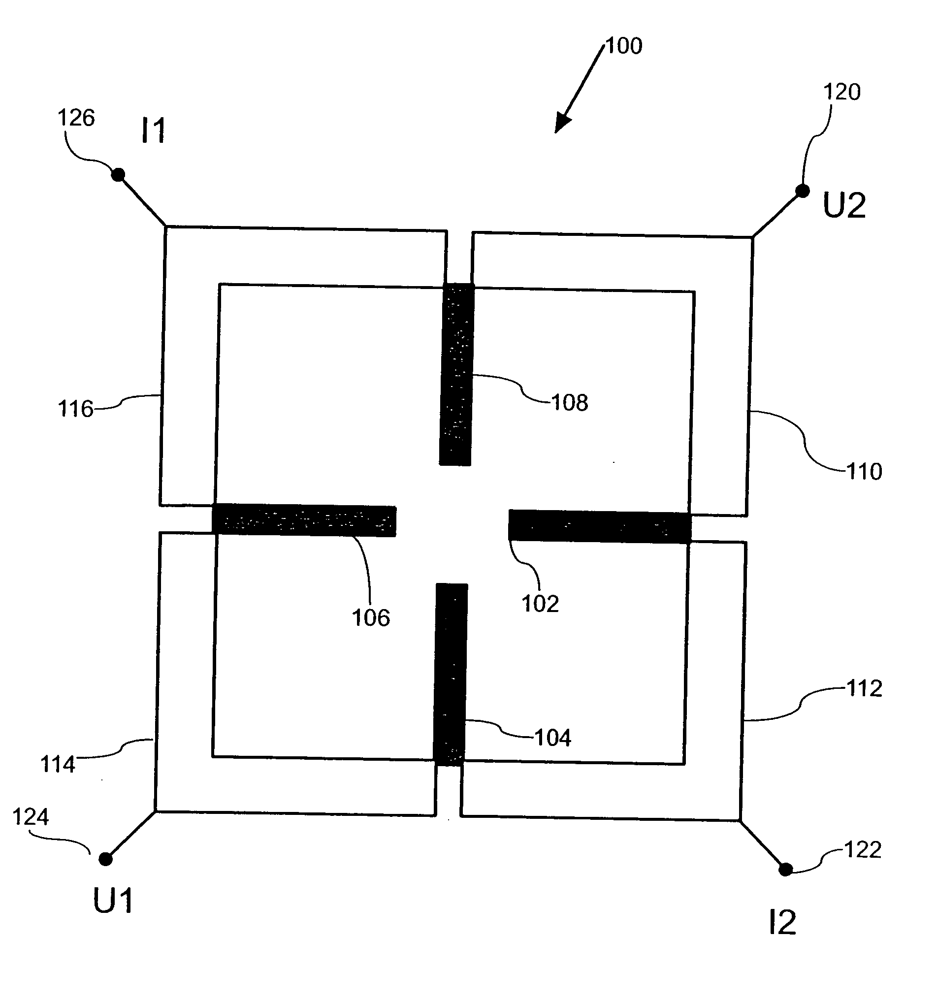
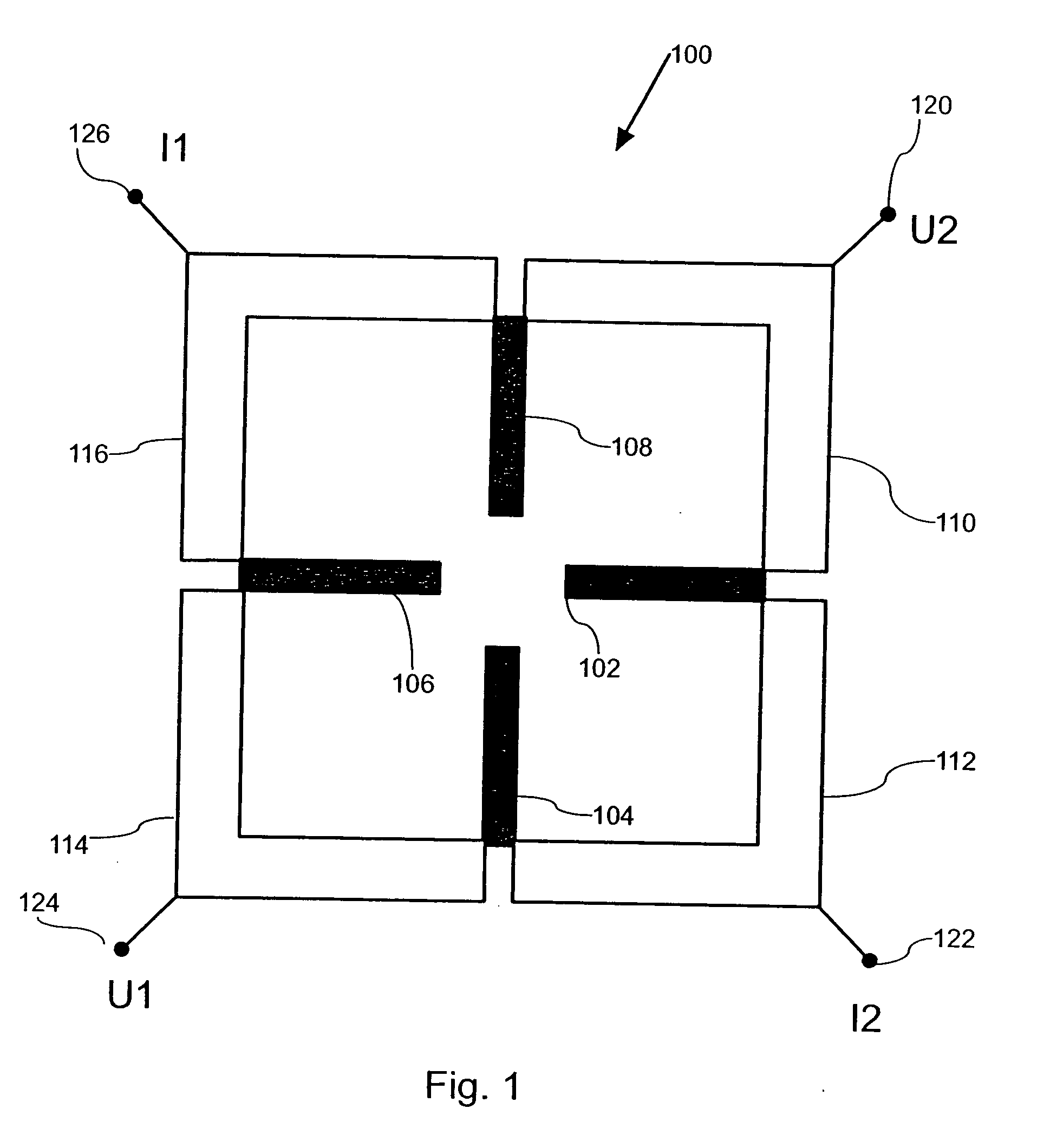
[0052]FIG. 1 shows a magnetic sensor 100 without flux guides. Therefore FIG. 1 only illustrates the electrical part of the magnetic sensor. The magnetic sensor 100 has four magnetoresistive elements 102, 104, 106, 108 that are connected via electrical conductors 110, 112, 114 and 116. Furthermore, the electrical circuit has four electrical connects 120, 122, 124 and 126.

[0053] The magnetoresistive elements are arranged in two pairs of two magnetoresistive elements featuring the same geometry, electrical properties as well as magnetic sensitivity. One pair of magnetoresistive elements has the horizontally aligned magnetoresistive elements 102 and 106 and the other pair of magnetoresistive elements has the vertically aligned magnetoresistive elements 108 and 104. Magnetoresistive element 102 is connected to magnetoresistive element 104 via the electrical conductor 112. Magnetoresistive element 102 is further connected to magnetoresistive element 108 via the electrical conductor 110. ...


PUM


Abstract

A magnetic sensor having at least a first and a second magnetoresistive element being non-parallel provides determination of the direction of a magnetic field. The at least first and second magnetoresistive elements are positioned along at least a first and a second elongated gap each of which separating at least a first and a second closely spaced planar area of soft-magnetic material serving as flux guides. The flux guides provide amplification of magnetic field components being perpendicular to the elongated direction of each gap. A variety of various magnetoresitive elements such as AMR elements or GMR-multilayer systems can effectively be used in order to detect the magnitude and/or the direction of the magnetic field. By appropriately designing the geometry of the flux guides, direction dependent gain factors can effectively be realized. This allows for a large detection range and sensitivity of the magnetic sensor.

Description

FIELD OF THE INVENTION [0001] The present invention relates to the field of detection of the orientation of a magnetic field and more particularly to the detection of an angular position of a rotatable element. DESCRIPTION OF THE RELATED ART [0002] The contactless determination of angular positions of a rotatable element can effectively be realized by making use of detecting the direction of a magnetic field characterizing the angular position of the rotatable element. By determining the direction of the magnetic field with the help of a magnetic sensor, the angular position of the rotatable element can be determined in a contactless way. Magnetic sensors known in the prior art predominantly make use of the Hall effect or some type of magnetoresistive effect. [0003] Making use of a magnetoresistive effect, a magnetic field that varies with the angle of rotation of a rotatable element can effectively be measured by means of a plurality of magnetoresistive elements featuring an electr...

Claims


Application Information

Patent Timeline
IPC IPC(8): G01B7/14G01B7/30G01R33/09
CPCG01R33/09
Inventor GRIMM, HUBERTPAUL, JOHANNESSCHAEFER, ROLF
Owner IBM CORP
Why Eureka
Try Eureka