Surface acoustic wave filter
a surface acoustic wave and filter technology, applied in the direction of impedence networks, electrical equipment, etc., can solve the problems of destroying the saw resonator, which is arranged between the terminal and the ground, reducing reliability, and reducing reliability, so as to achieve high reliability. the effect of measur
- Summary
- Abstract
- Description
- Claims
- Application Information
AI Technical Summary
Benefits of technology
Problems solved by technology
Method used
Image
Examples
first embodiment
[0017] (First Embodiment)
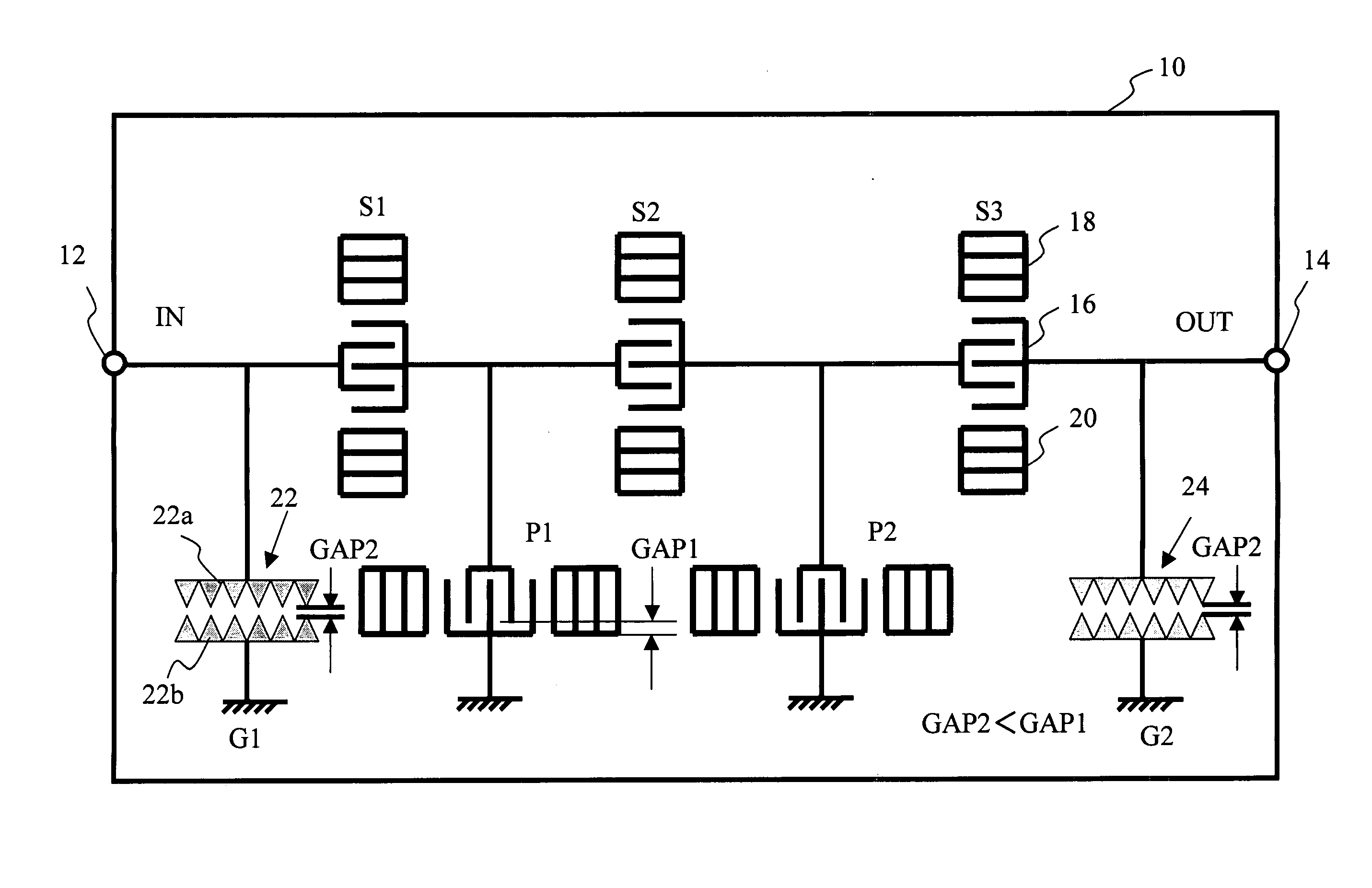
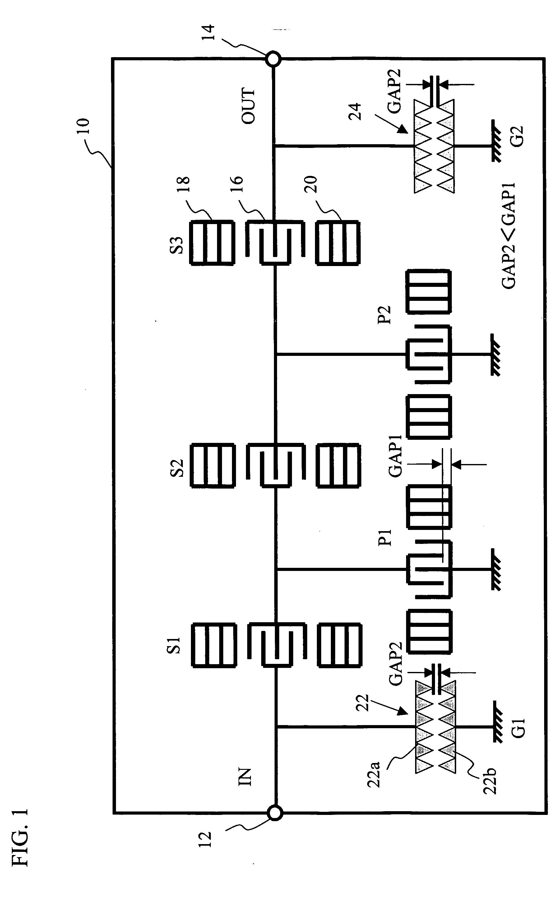
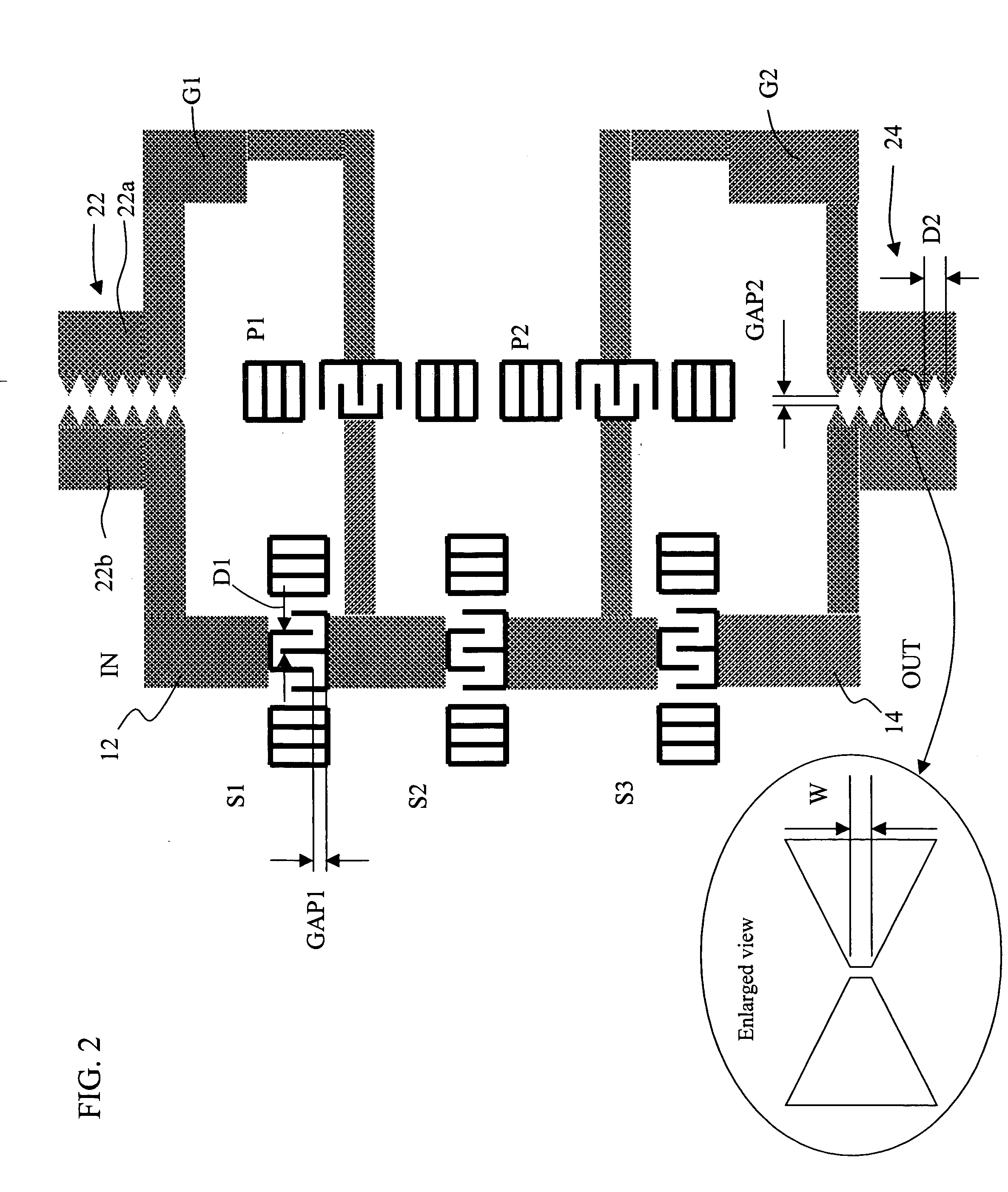
[0018]FIG. 1 shows a SAW filter in accordance with a first embodiment of the present invention. The SAW filter includes a piezoelectric substrate 10, multiple SAW resonators S1 through S3, P1, and P2 that are provided on the piezoelectric substrate 10, a signal input terminal 12, and a signal output terminal 14. These SAW resonators are connected in the ladder structure. The piezoelectric substrate 10 is made of a piezoelectric single crystal such as lithium tantalate (LT) or lithium niobate (LN). Each of the above-mentioned SAW resonators S1 through S3, P1, and P2 includes an IDT electrode 16 and reflection electrodes 18 and 20 that are arranged on both side of a propagation direction. For simplicity of the drawing, the referential numerals 16, 18, and 20 are shown in the SAW resonator S3 only. The IDT electrode 16 includes a pair of comb-like electrodes. The SAW resonators S1 through S3 are disposed in series arms in the ladder-type structure, and the SAW ...
second embodiment
[0024] (Second Embodiment)
[0025]FIGS. 3A and 3B show the SAW filter in accordance with a second embodiment of the present invention. FIG. 3A is a block diagram of the entire SAW filter. FIG. 3B shows an enlarged view of the discharge induction pattern. The SAW filter includes discharge induction patterns 32 and 34 in accordance with the second embodiment of the present invention. The discharge induction pattern 32 is arranged between the signal input terminal 12 and the ground G1. The discharge induction pattern 34 is arranged between the signal output terminal 14 and the ground G2. The discharge induction pattern 32 includes a pair of electrodes 32a and 32b that face each other. The electrodes 32a and 32b respectively include multiple sharp-pointed portions. The discharge induction pattern 32 includes multiple gaps having different sizes, which is different from the gaps in accordance with the first embodiment of the present invention. The discharge induction pattern 32 includes th...
PUM
 Abstract
Description
Claims
Application Information
 - R&D
- Intellectual Property
- Life Sciences
- Materials
- Tech Scout
- Unparalleled Data Quality
- Higher Quality Content
- 60% Fewer Hallucinations
Browse by: Latest US Patents, China's latest patents, Technical Efficacy Thesaurus, Application Domain, Technology Topic, Popular Technical Reports.
© 2025 PatSnap. All rights reserved.Legal|Privacy policy|Modern Slavery Act Transparency Statement|Sitemap|About US| Contact US: help@patsnap.com


