Radiometry device

a technology of a radiometer and a temperature sensor, which is applied in the direction of heat measurement, optical radiation measurement, instruments, etc., can solve the problem of difficult accurate measurement of the temperature of the radiator, and achieve the effect of accurate measurement of the temperature of the object and highly reliable measurements

Active Publication Date: 2020-10-27
HIGH ENERGY ACCELERATOR RESEARCH ORGANIZATION
View PDF0 Cites 0 Cited by
  • Summary
  • Abstract
  • Description
  • Claims
  • Application Information

AI Technical Summary

Benefits of technology

[0051]The present invention calibrates the temperature of an object using a blackbody in a quasi-thermal equilibrium state at an ultralow temperature in vacuo. Consequently, the present invention can accurately measure the temperature of the object without adverse effects of disturbances affecting the object, and can achieve highly reliable measurements.
[0052]In particular, maintaining the blackbody in vacuo of 10−4 Pa or lower and at an ultralow temperature of 30 K or lower can reduce, to 1 / 10 or less, the temperature error between the measured temperature of the radiator (object) and the temperature of the object to be obtained (i.e., the temperature of the blackbody defined by Planck's formula).

Problems solved by technology

Unfortunately, the above methods are methods of measuring radiation while being directly or indirectly affected by disturbances due to the external environment.
Consequently, there is a problem in that accurate measurement of the radiator temperature is difficult.

Method used


Image

  • Radiometry device
  • Radiometry device
  • Radiometry device

Examples


embodiment 1

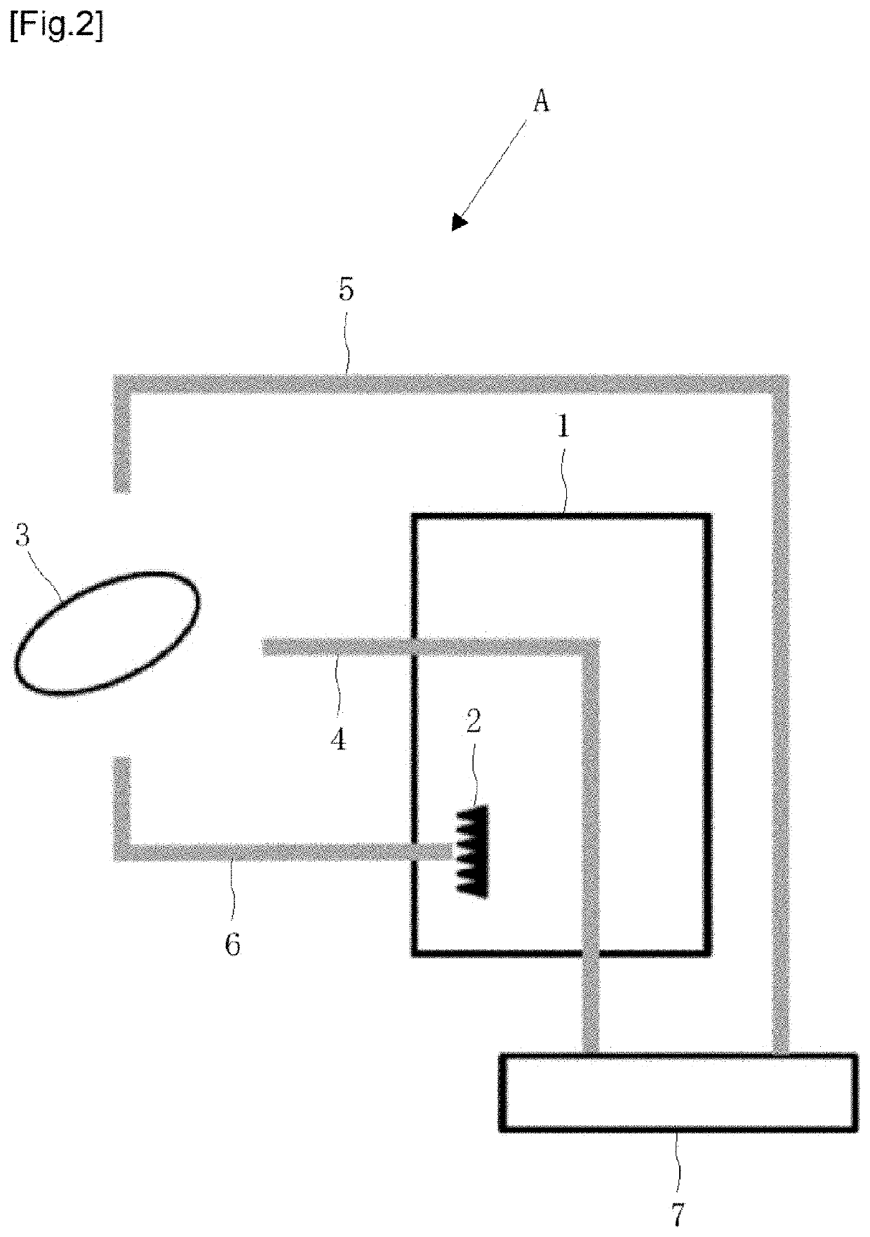
[0060]FIG. 2 is a schematic diagram of a radiometry device of the present invention. The radiometry device A of the present invention includes: a vacuum ultralow temperature thermostatic chamber 1 that keeps the inside at an ultralow temperature in vacuo; a first optical path 4 that is provided in the vacuum ultralow temperature thermostatic chamber 1 and amplifies radiation at a first frequency; a blackbody 2 provided in the vacuum ultralow temperature thermostatic chamber 1; a second optical path 5 that is provided outside of the vacuum ultralow temperature thermostatic chamber 1 and amplifies radiation at a second frequency; a polarization filter 3 that is provided outside of the vacuum ultralow temperature thermostatic chamber 1 and separates the radiation into polarized light beams; a third optical path 6 through which radiation from the blackbody 2 enters the polarization filter 3; and a spectrum analyzer 7 that analyzes a signal having passed through the first optical path 4 ...


PUM

PropertyMeasurementUnit
temperatureaaaaaaaaaa
boiling pointaaaaaaaaaa
radiator temperatureaaaaaaaaaa

Abstract

The present invention separates radiation from an object by a polarization filter 3 into polarized light beams, causes one of the beams to enter a spectrum analyzer 7 through a first optical path, causes the other to enter the spectrum analyzer 7 through a second optical path, and measures the two-color ratio, while causes radiation of a blackbody 2 placed in a vacuum ultralow temperature thermostatic chamber 1 in a quasi-thermal equilibrium state at an ultralow temperature in vacuo to enter the polarization filter 3 through a third optical path, separates the radiation into polarized light beams, causes the beams to each enter the same optical paths as the respective optical paths for the radiation of the object, causes the beams to enter the spectrum analyzer 7, measures the two-color ratio, and accurately obtains the temperature of the object on the basis of these two two-color ratios.

Description

TECHNICAL FIELD[0001]The present invention relates to a radiometry device. More specifically, the present invention relates to a radiometry device that uses a blackbody in a quasi-thermal equilibrium state at an ultralow temperature in vacuo in order to measure the temperature of radiation of an object (radiator) present in nature (called graybody radiation) (abbreviated as radiator temperature), and accurately measures the radiator temperature by calibrating the temperature of the radiator according to two-color thermometry based on Planck's formula.BACKGROUND ART[0002]As methods and devices that measure the radiator temperature in a non-contact manner, for example, Patent Literatures 1 to 4 and Non Patent Literature 1 have been known.[0003]Patent Literature 1 discloses a method of obtaining the radiator temperature by splitting the radiation from a radiator into two polarized components, measuring the respective spectral radiances L1 and L2, and compensating the effect of backgrou...

Claims


Application Information

Patent Timeline
Patent Type & Authority Patents(United States)
IPC IPC(8): G01J5/00G01J5/10G01J5/46G01K1/00G01K15/00G01J5/58G01J5/52G01J5/06G01J5/60G01J5/02G01J5/08
CPCG01J5/60G01J5/061G01J5/0003G01J5/0825G01J5/58G01J5/46G01J5/602G01J5/02G01J5/0285G01J5/10G01J5/522G01J2005/586G01J5/068G01J5/59G01J5/53
Inventor TAJIMA, OSAMUNAGASAKI, TAKETO
Owner HIGH ENERGY ACCELERATOR RESEARCH ORGANIZATION
Why Eureka
Try Eureka