Radiation monitoring equipment

a technology of radiation monitoring equipment and equipment, applied in the direction of x/gamma/cosmic radiation measurement, instruments, greenhouse gas reduction, etc., can solve the problem of visible noise, achieve high reliability, wide range, and high reliability of measuremen

Active Publication Date: 2018-02-08
MITSUBISHI ELECTRIC CORP
View PDF58 Cites 2 Cited by
  • Summary
  • Abstract
  • Description
  • Claims
  • Application Information

AI Technical Summary

Benefits of technology

[0018]Furthermore, the radiation monitoring equipment according to the present invention, wherein if the operation unit judges that the number of times deviated from the permissible range is not zero, the operation unit judges whether the number of times deviated from the permissible range is within the permissible number of times or not, if the operation unit judges that the number of times deviated from the permissible range is out of the permissible number of times, the operation unit performs the regular processing and further resets the number of times deviated from the permissible range, if the operation unit judges that the number of times deviated from the permissible range is within the permissible number of times, the operation unit subtracts a cumulated count at an operation cycle just before the first noise processing from the cumulated count (previous time) to find a difference, and divides the difference with the number of times deviated from the permissible range+1 to find a first average real count, and judges whether the first average real count is within the permissible range or not, if the operation unit judges that the first average real count is within the permissible range, the operation unit performs a second noise processing and further resets the number of times deviated from the permissible range, and further wherein the second noise processing includes; a step for replacing a real count deviated from the permissible range with the first average real count, a step for obtaining a moving average counting rate (this time) based on a data row of real counts after replacement, and a step for converting the moving average counting rate (this time) into an engineering value and outputting the value. Then, an average real count is calculated based on the cumulated counts just before and just after the noise invasion. The real counts among the invasion period are interpolated to up-date the data row having a preset number of real counts in chronological order. Thereby, it is possible to offer the radiation monitoring equipment which is capable of highly reliable measurement, with no substantial missing measurements. Besides that, prevented are fluctuations by the reduction in the number of data concerning the calculation of the moving average counting rate and the stable accuracy in measurement can be acquired.
[0019]Furthermore, the radiation monitoring equipment according to the present invention, wherein if the operation unit judges that the first average real count is not within the permissible range, the operation unit performs a third noise processing and furthermore resets the number of times deviated from the permissible range, and further wherein the third noise processing includes; a step for obtaining a second average real count by averaging a real count (this time) and a latest real count within the permissible range, a step for replacing a real count deviated from the permissible range with the second average real count, a step for obtaining a moving average counting rate (this time) based on a data row of real counts after replacement, and a step for converting the moving average counting rate into an engineering value and outputting the value. Then, an average real count is calculated based on the cumulated counts just before and just after the noise invasion. The real counts among the invasion period are interpolated to up-date the data row having a preset number of real counts in chronological order. Thereby, it is possible to offer the radiation monitoring equipment which is capable of highly reliable measurement, with no substantial missing measurements. Besides that, prevented are fluctuations by the reduction in the number of data concerning the calculation of the moving average counting rate and the stable accuracy in measurement can be acquired.BRIEF EXPLANATION OF DRAWINGS
[0020]FIG. 1 is a drawing for showing constituent elements of the radiation monitoring equipment in accordance with the embodiments of the present invention.
[0021]FIG. 2 is a signal waveform diagram for explaining the operation of the radiation monitoring equipment in accordance with the embodiments of the present invention, and is a drawing for showing the form of the current signal outputted from a radiation detector.
[0022]FIG. 3 is a signal waveform diagram for explaining the operation of the radiation monitoring equipment in accordance with the embodiments of the present invention, and is a drawing for showing schematically the waveform of a saw-tooth wavelike pulse.

Problems solved by technology

Because the electric charge of discharge is offset by the electric charge of charge, a noise appears in sight.

Method used


Image

  • Radiation monitoring equipment
  • Radiation monitoring equipment
  • Radiation monitoring equipment

Examples


embodiment 1

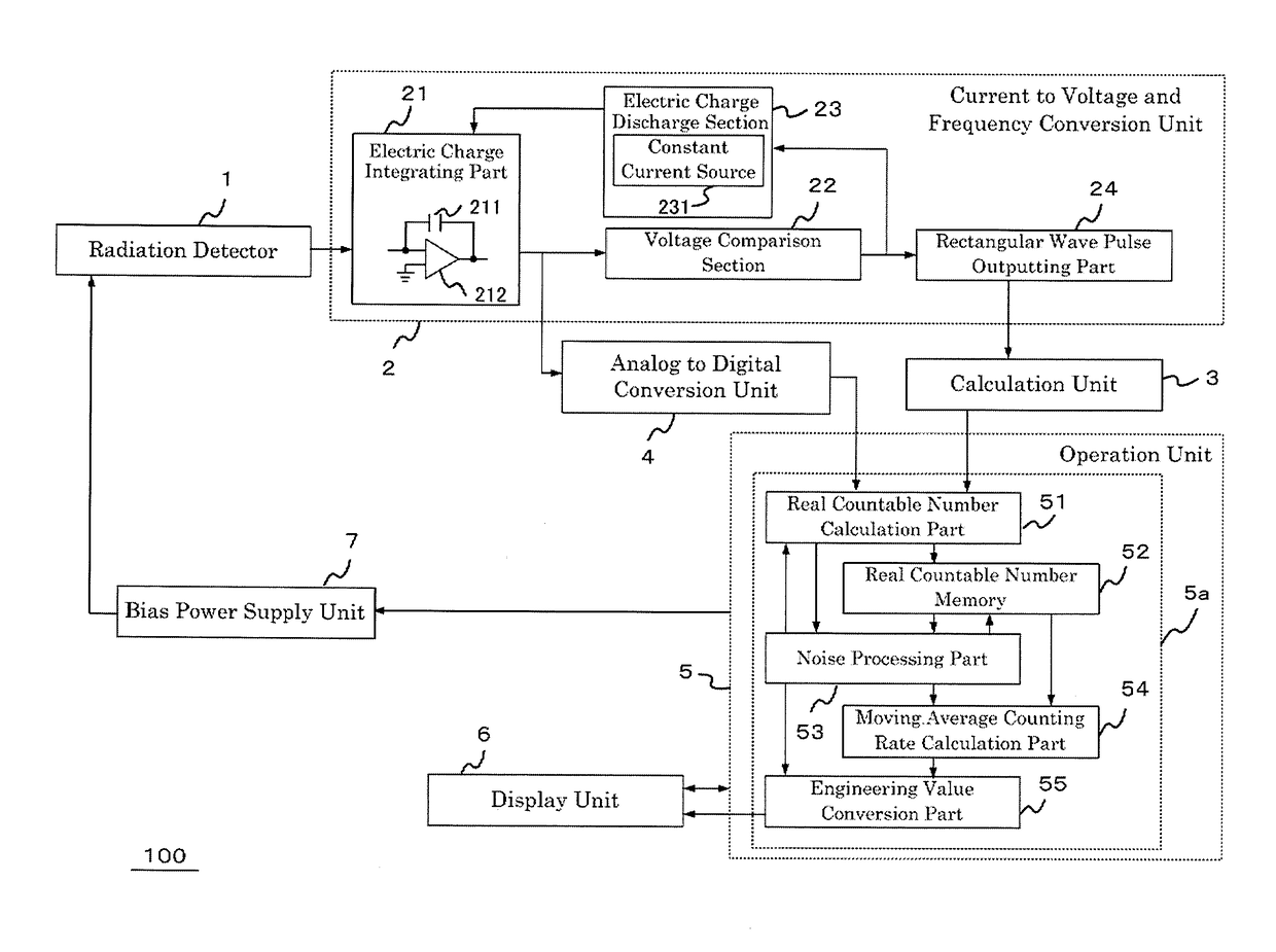
[0040]FIG. 1 is a block diagram for showing the configuration of the radiation monitoring equipment 100 according to the embodiments of the present invention. As shown in the drawing, the radiation monitoring equipment 100 contains a radiation detector 1, a current to voltage and frequency conversion unit 2 (a first conversion unit), a calculation unit 3, an analog to digital conversion unit 4 (a second conversion unit), an operation unit 5, a display unit 6, a bias power supply unit 7 and the like. The radiation detector 1 is connected to the input side of the electric charge integrating part 21 of the current to voltage and frequency conversion unit 2. The radiation detector 1 outputs current signals generated by the incident radiation to the current to voltage and frequency conversion unit 2.

[0041]The current to voltage and frequency conversion unit 2 includes an electric charge integrating part 21, a voltage comparison section 22, an electric charge discharge section 23, and a r...

embodiment 2

[0084]A radiation monitoring equipment 100 in accordance with Embodiment 2 is explained based on FIG. 8, FIG. 14, FIG. 15 and FIG. 16. The radiation monitoring equipment 100 in accordance with Embodiment 2 operates fundamentally according to the flow chart shown in FIG. 8. According to Embodiment 2, as shown in the flow chart of FIG. 14, the process of step SO61 is added between step S06 and step SO7, which are employed in the flow chart of FIG. 8 of Embodiment 1. If the judgment of step S06 is Yes, “Q=1” and “Date; year, month, day, time” are memorized at step S061. In a similar manner, as shown in the flow chart of FIG. 15, the process of step S141 is added between step S14 and stop S16, which are employed in the flow chart of FIG. 8. “End of D2” and “Date; year, month, day, time” are memorized at step S141.

[0085]Further, as shown in the flow chart of FIG. 16, the process of step S151 is added between step S15 and step S16 of the flow chart of FIG. 8. “End of D3” and “Date; year, ...

embodiment 3

[0087]A radiation monitoring equipment 100 in accordance with Embodiment 3 is explained based on FIG. 8, FIG. 17 and FIG. 18. The radiation monitoring equipment 100 in accordance with Embodiment 3 operates fundamentally according to the flow chart shown in FIG. 8. It is noted that in Embodiment 3, step S142 is added, as shown in the flow chart of FIG. 17, between step S141 and step S16, which are employed in the flow chart of FIG. 15 of Embodiment 2. In step S142, the number of times of the noise processing (D2) is accumulated, and the cumulated number of times of D2 processing is memorized. Step S152 is similarly added between step S151 and step S16 of the flow chart of FIG. 16, like the flow chart of FIG. 18. In step S152, the number of times of noise processing (D3) is accumulated, and the cumulated number of times of D3 processing is memorized.

[0088]It is made to display those memorized contents on the display unit 6 by requesting from the display unit 6. The maintainability of ...


PUM


Abstract

The operation unit of radiation monitoring equipment reads in a real countable number (this time) and a cumulated countable number (previous time) in a every operational cycle, and judges whether the real countable number (this time) is within a permissible range, if the real countable number (this time) is judged to be within the permissible range, it is judged whether a number of times deviated from the permissible range is equal to zero or not, if the number of times deviated from the permissible range is judged to be equal to zero, a regular processing is performed, if the real countable number (this time) is judged to be out of a permissible range, 1 is added to the number of times deviated from the permissible range and further it is judged whether the added number of times deviated from the permissible range is equal to 1 or not.

Description

FIELD OF THE INVENTION[0001]The present invention relates to radiation monitoring equipment, and in particular, to the radiation monitoring equipment which measures a dose rate and the like, by detecting a current signal outputted from a radiation detector.BACKGROUND[0002]In order to measure a dose rate and others in the living space, radiation monitoring equipment is installed around a nuclear power plant, a nuclear fuel reprocessing plant, an institution for radiation application, their affiliated facilities and the like (see Patent Documents 1-6, for example). The radiation monitoring equipment needs to measure dose rates in a wide range, from the normal radiation level to the radiation level supposing an accident, with sufficient accuracy. In order to cover the current in a minute quantity and in a wide range, an ion chamber, for example, is used for the radiation detector of the radiation monitoring equipment. If radiation acts on the ion chamber of the radiation detector, a ve...

Claims


Application Information

Patent Timeline
Patent Type & Authority Applications(United States)
IPC IPC(8): G01T1/17G01T1/185
CPCG01T1/185G01T1/17G01T1/02G01T1/023G01T1/171G01T1/20G01T1/208Y02E30/30
Inventor EGUCHI, KAZUHIRO
Owner MITSUBISHI ELECTRIC CORP
Why Eureka
Try Eureka