Surface acoustic wave filter

a surface acoustic wave and filter technology, applied in the direction of impedence networks, electrical equipment, etc., can solve the problems of destroying the saw resonator, which is arranged between the terminal and the ground, and the saw filter cannot be protected from static electricity any longer, so as to achieve high reliability. the effect of measur

Active Publication Date: 2005-07-14
TAIYO YUDEN KK
View PDF13 Cites 2 Cited by
  • Summary
  • Abstract
  • Description
  • Claims
  • Application Information

AI Technical Summary

Benefits of technology

[0007] It is a general object of the present invention to solve the above-mentioned problem and provide the SAW filter with a highly reliable measure against the static electricity.
[0008] According to an aspect of the present invention, there is provided a surface acoustic wave (SAW) filter having a plurality of SAW resonators, preferably, the plurality of SAW resonators are connected in series, the plurality of SAW resonators are provided either between a signal input terminal and a ground that is the closest thereto or between a signal output terminal and a ground that is the closest thereto, and the plurality of SAW resonators having substantially equal electrostatic capacitances. It is thus possible to protect the SAW resonators without providing a sacrificial electrode for electrostatic breakdown, and thereby possible to configure the SAW filter having a high reliability against the electrostatic discharge.

Problems solved by technology

As a result, the SAW resonator, which is arranged between the terminal and the ground, is destroyed.
However, there is the problem in that once the sacrificial electrode is broken, the SAW filter cannot be protected from the static electricity any longer.

Method used


Image

  • Surface acoustic wave filter
  • Surface acoustic wave filter
  • Surface acoustic wave filter

Examples


first embodiment

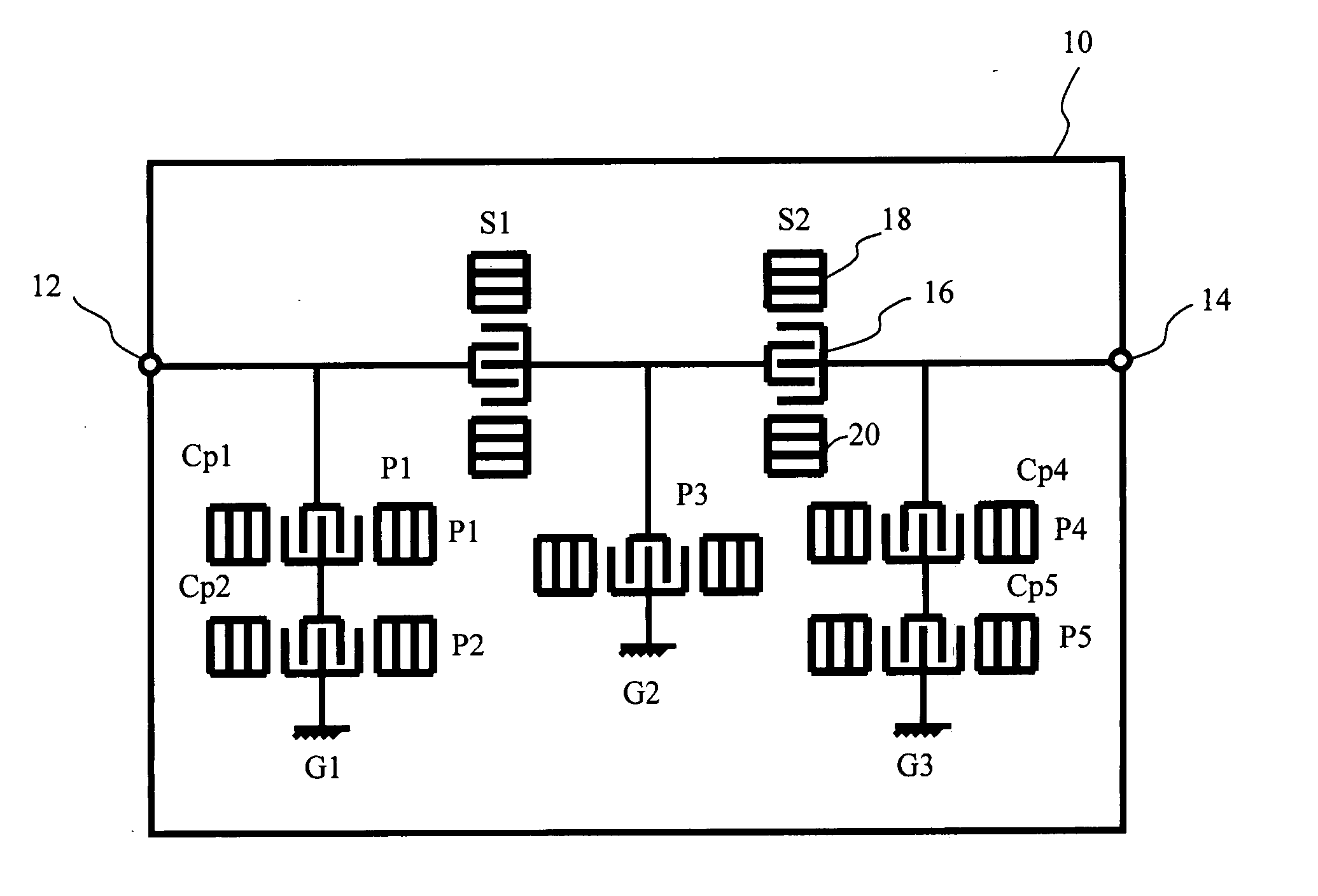
[0020]FIG. 1 shows a SAW filter in accordance with a first embodiment of the present invention. The SAW filter includes a piezoelectric substrate 10, multiple SAW resonators S1, S2, P1, P2, P3, P4, and P5 that are provided on the piezoelectric substrate 10, a signal input terminal 12, and a signal output terminal 14. These SAW resonators are connected in the ladder structure. The piezoelectric substrate 10 is made of a piezoelectric single crystal such as lithium tantalite (LT) or lithium niobate (LN). Each of the above-mentioned SAW resonators S1, S2, P1, P2, P3, P4, and P5 includes an IDT electrode 16 and reflection electrodes 18 and 20 that are arranged on both side of a propagation direction. For simplicity of the drawing, the referential numerals 16, 18, and 20 are shown in the SAW resonator S2 only. The IDT electrode 16 includes a pair of comb-like electrodes. Each of the SAW resonators S1 and S2 is disposed in a series arm in the ladder-type structure, and each of the SAW res...

second embodiment

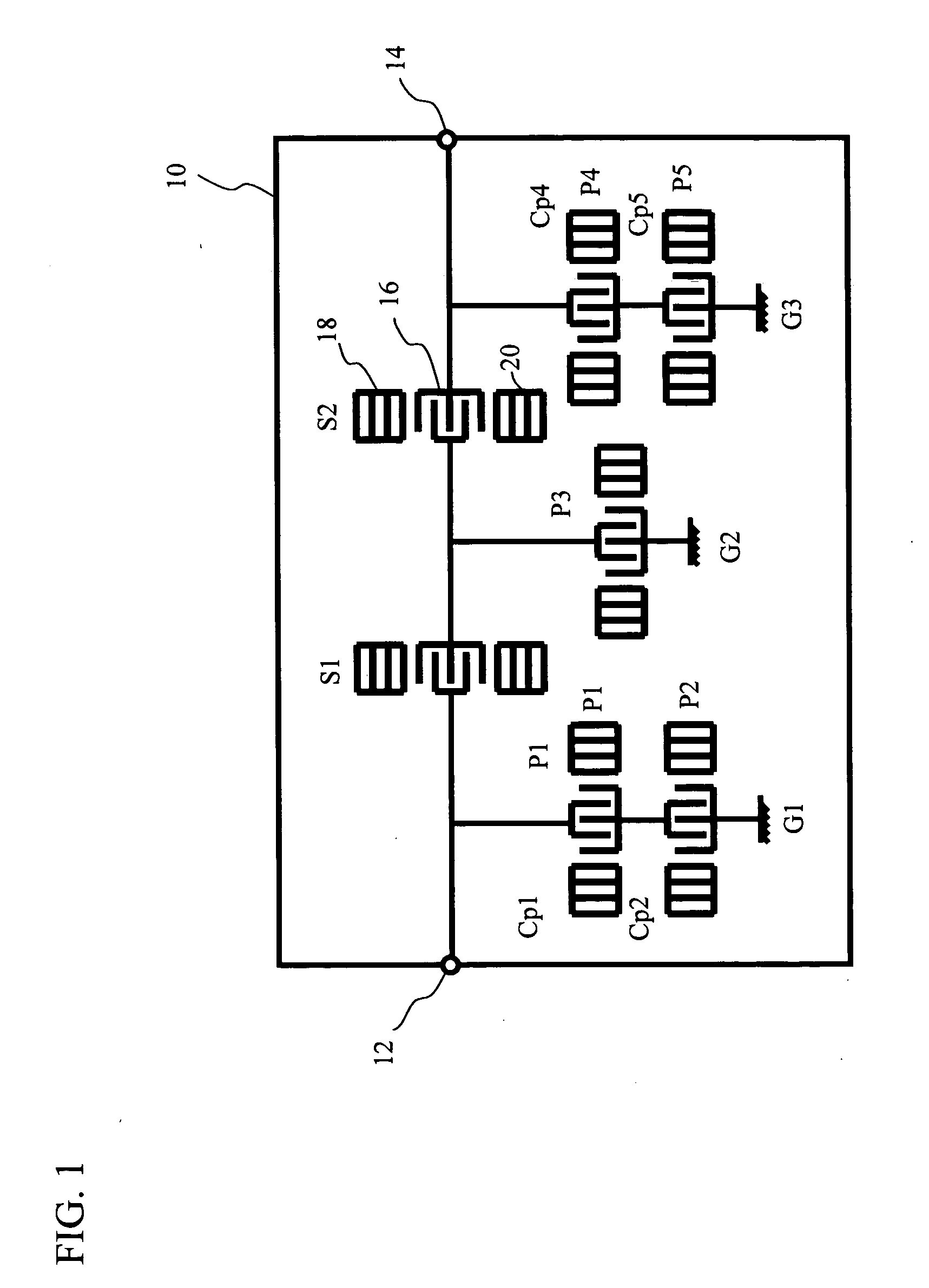
[0026]FIG. 2 shows the SAW filter in accordance with a second embodiment of the present invention. The SAW filter includes the piezoelectric substrate 10, multiple SAW resonators S1 through S4 and P1 through P3, the signal input terminal 12, and the signal output terminal 14. These SAW resonators are arranged in the ladder type. The SAW resonators S1 through S4 and P1 through P3 determine the filter characteristics. In accordance with the second embodiment of the present invention, the multiple resonators S1 and P1, which are connected in series, are arranged between the signal input terminal 12 and the ground G1 that is the closest thereto. The multiple resonators S4 and P3, which are connected in series, are arranged between the signal output terminal 14 and the ground G3 that is the closest thereto. The electrostatic capacitance Cs1 of the SAW resonator S1 and the electrostatic capacitance Cp1 of the SAW resonator P1 are substantially equal, and the electrostatic capacitance Cs4 ...

third embodiment

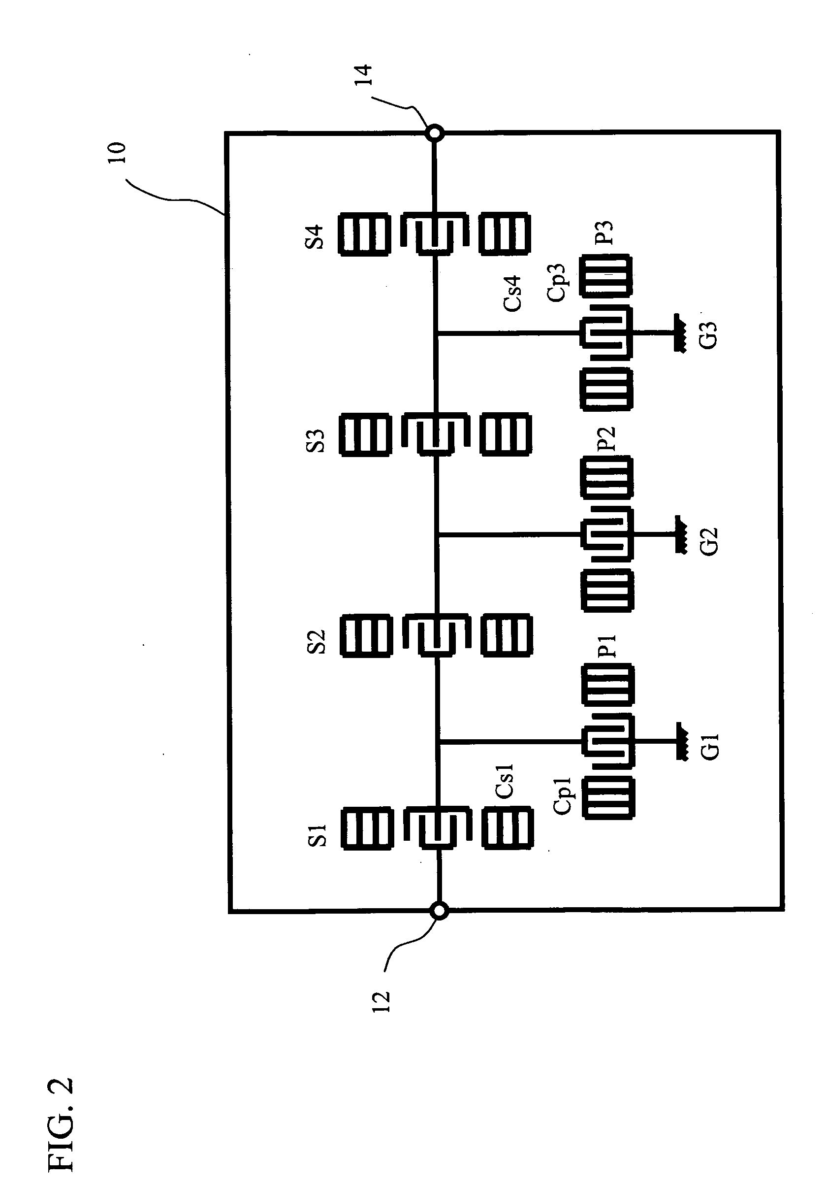
[0028]FIG. 3 shows the SAW filter in accordance with a third embodiment of the present invention. This filter is configured to combine the first embodiment and the second embodiment of the present invention. More specifically, the parallel-arm resonators P1 and P2, which are connected in series, are arranged between the signal input terminal 12 and the ground G1 that is the closest thereto. The series-arm resonator S2 and parallel-arm resonator P3, which are connected in series, are arranged between the signal output terminal 14 and the ground G2 that is the closest thereto. The electrostatic capacitance Cp1 of the parallel-arm resonator P1 and the electrostatic capacitance Cp2 of the parallel-arm resonator P2 are substantially equal. Cp1 divided by Cp2 is equal to 0.9 to 1.1. The electrostatic capacitance Cs2 of the series-arm resonator S2 and the electrostatic capacitance Cp3 of the parallel-arm resonator P3 are substantially equal. Cs2 divided by Cp3 is equal to 0.9 to 1.1. Part ...


PUM


Abstract

A SAW filter includes multiple SAW resonators. The multiple SAW resonators, which are connected in series, are connected any one of between a signal input terminal and a ground that is the closest thereto and between a signal output terminal and another ground that is the closest thereto. The SAW resonators have substantially equal electrostatic capacitances. It is thus possible to protect the SAW resonators without providing a sacrificial electrode for electrostatic breakdown, and thereby possible to configure the SAW filter having a high reliability against the electrostatic discharge.

Description

BACKGROUND OF THE INVENTION [0001] 1. Field of the Invention [0002] This invention generally relates to a surface acoustic wave (hereinafter simply referred to as SAW) filter having a SAW resonator, and more particularly, to a technique for protecting the SAW filter from electrostatic discharge (referred to as ESD). [0003] 2. Description of the Related Art [0004] In recent years, wireless devices such as mobile telephones have been downsized rapidly, highly advanced, and highly improved in quality. A high-frequency circuit of the wireless device employs the filter having the SAW resonator. The filter structure includes a ladder-type filter and a multimode filter. The ladder-type filter is composed of multiple SAW resonators that are connected in a ladder structure. The multi-mode filter includes a double-mode SAW filter (referred to as DMS), for example. The SAW resonator includes a pair of comb-like electrodes that face each other on a piezoelectric substrate. This comb-like electr...

Claims


Application Information

Patent Timeline
Patent Type & Authority Applications(United States)
IPC IPC(8): H03H9/00H03H9/145H03H9/64
CPCH03H9/0061H03H9/6483H03H9/6469H03H9/02921H03H9/145H03H9/64
Inventor FURUSATO, HIROYUKIKAWACHI, OSAMU
Owner TAIYO YUDEN KK
Why Eureka
Try Eureka