Triple-band offset hybrid antenna using shaped reflector

a hybrid antenna and reflector technology, applied in the field of offset hybrid antennas, can solve the problems of tracking errors, device speed and tracking speed slowdown, many limitations in view of manufacturing, price and integration, etc., and achieve the effect of reducing blocking loss

Inactive Publication Date: 2005-06-30
ELECTRONICS & TELECOMM RES INST
View PDF3 Cites 30 Cited by
  • Summary
  • Abstract
  • Description
  • Claims
  • Application Information

AI Technical Summary

Benefits of technology

[0009] It is, therefore, an object of the present invention to provide a triple-band offset hybrid antenna having a shaped reflector for reducing a block

Problems solved by technology

If the phased array antenna system must have characteristics of a multi-band, a high gain and a wide beam scan sector, there are many limitations in views of manufacturing, price and integration for satisfying the above mentioned requirements in order to manufacturing the phased array antenna system.
However, the conventional antenna having the mechanical positioning device has

Method used


Image

  • Triple-band offset hybrid antenna using shaped reflector
  • Triple-band offset hybrid antenna using shaped reflector
  • Triple-band offset hybrid antenna using shaped reflector

Examples


first embodiment

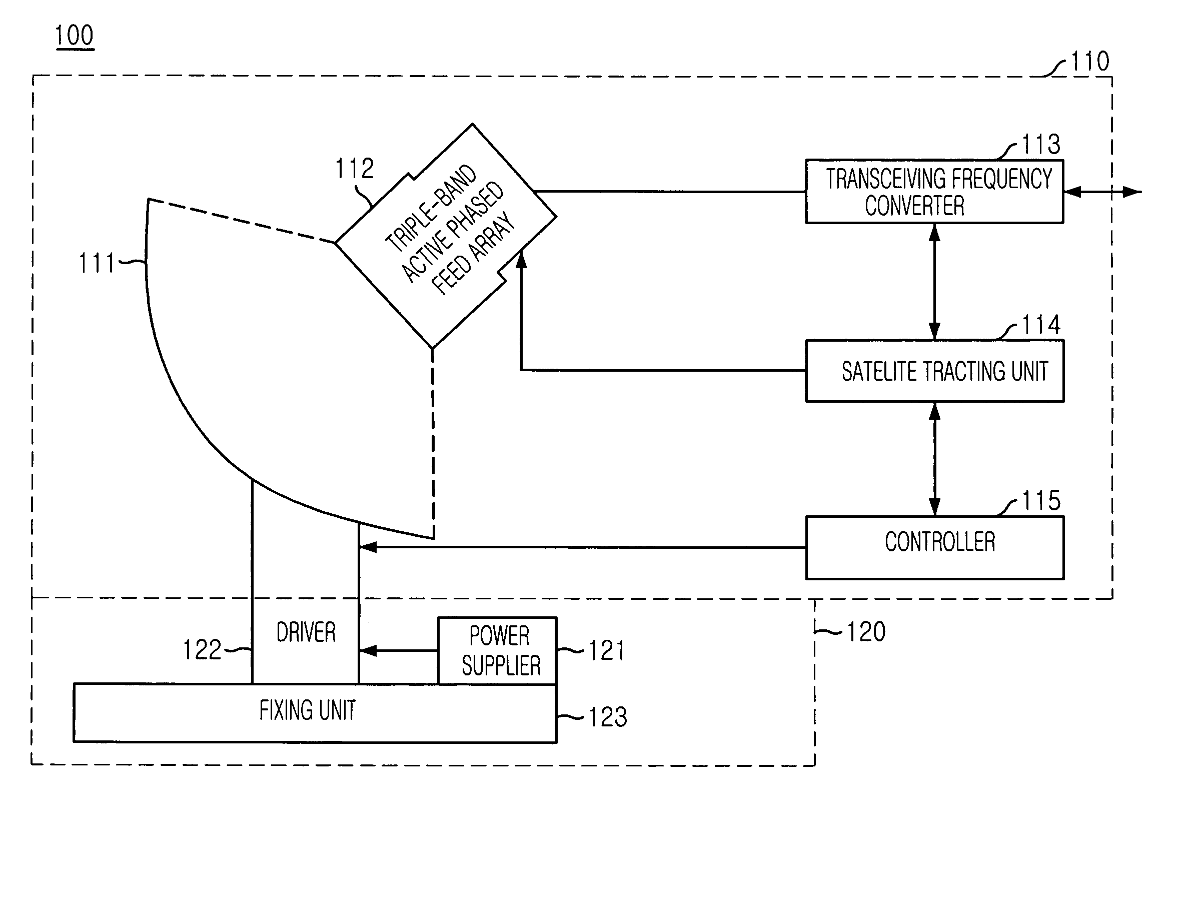
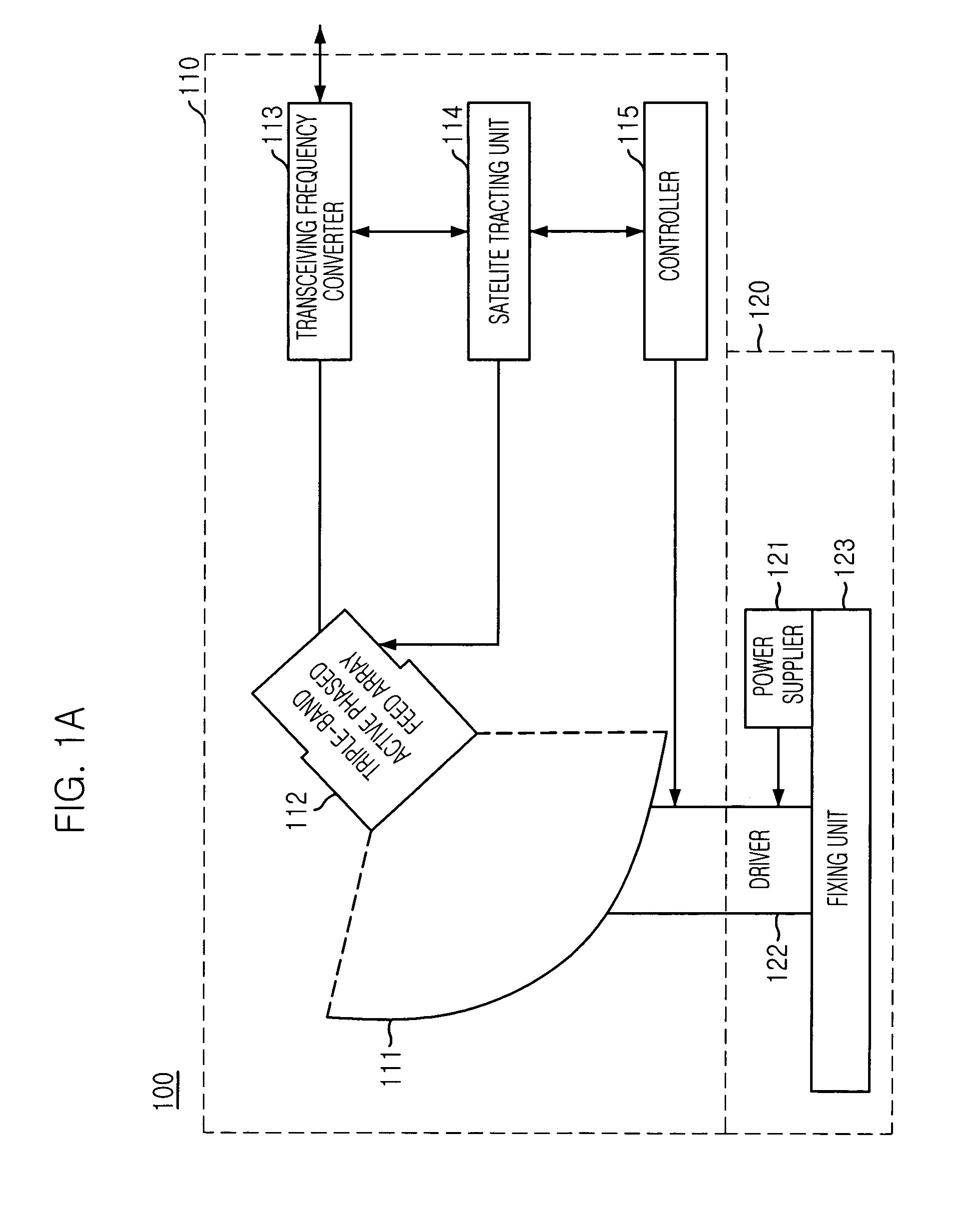
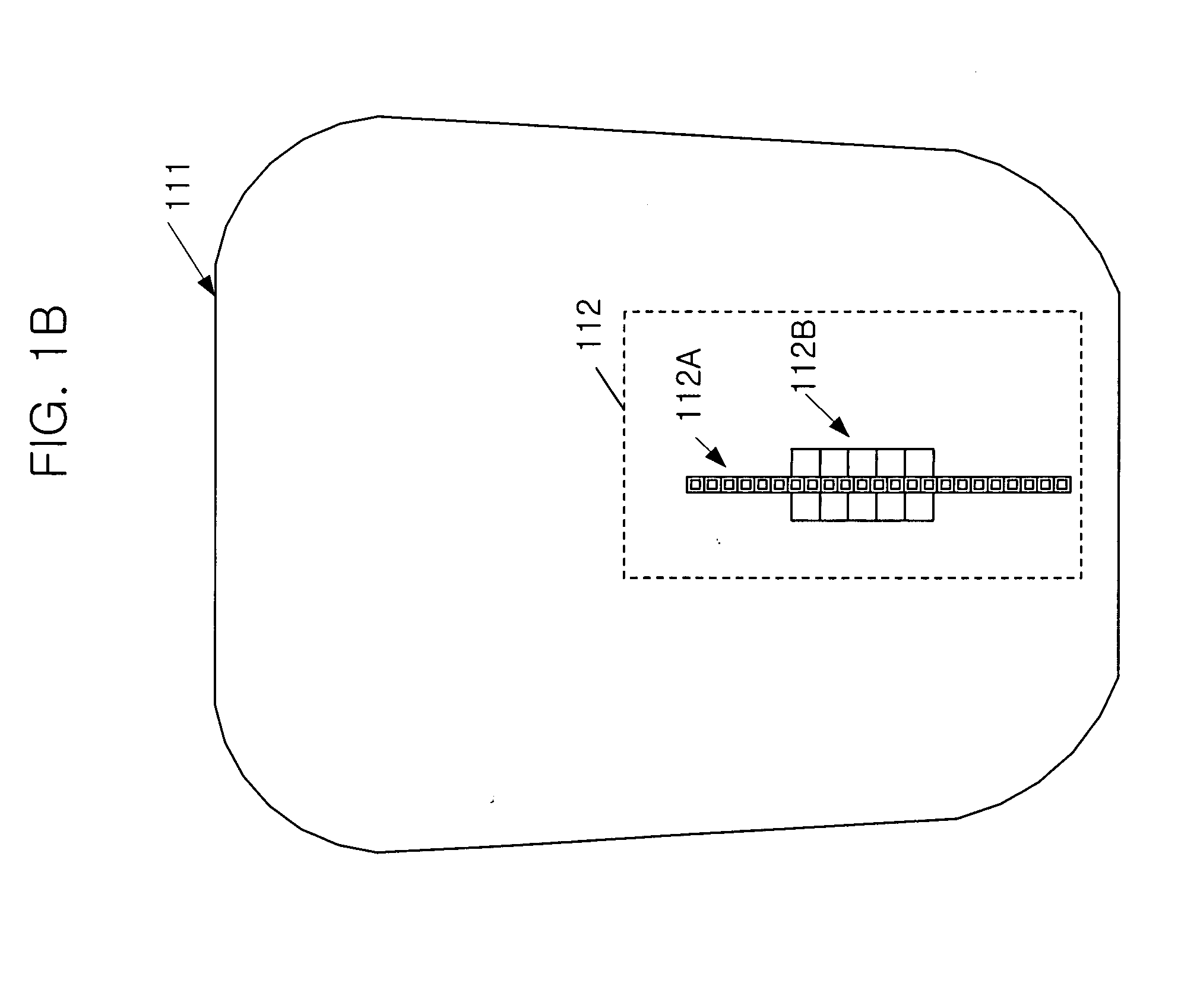
[0028]FIGS. 1A and 1B is a diagram illustrating a triple-band hybrid antenna in accordance with the present invention.

[0029] As shown, the triple-band offset hybrid antenna 100 includes a rotating unit 110 and a fixing unit 120.

[0030] The fixing unit 120 includes a power supplier 121, a motor driving unit 122 and a mount 123. The fixing unit 120 is a mounting structure for supporting the rotating unit 110 of the triple-band offset hybrid antenna 100.

[0031] The rotating unit 110 includes a shaped reflector 111, a triple-band active phased feed array 112, a transceiving frequency converter 113, a satellite tracking unit 114 and a controller 115. The triple-band active, phased feed array 112 is offset from axis of the shaped reflector 111 for reducing a blocking loss and for obtaining lower sidelobe level. That is, the triple-band active phased feed array 113 is separately implemented from the shaped reflector 111.

[0032] The power supplier 121 provides direct current (DC) powers to ...

second embodiment

[0051]FIG. 7 is a top view of triple-band offset hybrid antenna with a shaped reflector in accordance with the present invention.

[0052] As shown in FIG. 7, the triple-band offset hybrid antenna 700 includes a shaped reflector 720 and a triple-band active phased feed array 710. The triple-band offset hybrid antenna 700 has exactly same structure comparing to the triple-band offset hybrid antenna 100 of the present invention excepting a triple-band active phased feed array 710. Accordingly, detailed explanation of the shaped reflector 720 including the fixing unit 120 and the rotation unit 110 is omitted excepting the triple-band active phased feed array 710.

[0053] The triple-band active phased feed array 710 includes Ka / K bands feed array 711 for transceiving Ka / K bands RF signal and a Ku band feed array 712 for receiving a Ku band RF signal.

[0054] As shown in FIG. 7, the triple-band active phased feed array 710 is arranged on a focal line where the signal reflected from the shaped...


PUM


Abstract

A triple-band offset hybrid antenna having a shaped reflector is disclosed. The triple-band offset hybrid antenna includes: a shaped reflector reflecting a K/Ku bands RF signals received from a satellite to focus an energy of the K/Ku band RF signals on a focal line and reflecting a Ka band RF transmitting signal; and a triple-band active phased feed array receiving the reflected K/Ku bands RF signals from the shaped reflector and radiating the Ka band RF transmitting signal to the shaped reflector, wherein the triple-active feed array including Ka/K bands feed array for transceiving Ka/K bands RF signal and a Ku band feed array for receiving a Ku band RF signal.

Description

FIELD OF THE INVENTION [0001] The present invention relates to an offset hybrid antenna; and, more particularly, to a triple-band offset hybrid antenna using a shaped reflector for a satellite communication. DESCRIPTION OF RELATED ARTS [0002] Generally, an antenna structure is designed by considering various factors of the antenna such as a performance, a price and an implementation environment. [0003] A conventional phased array antenna system having an electronic tracking system can track a target in high speed by using an electronic beam and thus, the conventional phased array antenna system has been widely used for a military ladder system that requires a high speed and an accurate tracking. [0004] If the phased array antenna system must have characteristics of a multi-band, a high gain and a wide beam scan sector, there are many limitations in views of manufacturing, price and integration for satisfying the above mentioned requirements in order to manufacturing the phased array...

Claims


Application Information

Patent Timeline
IPC IPC(8): H01Q5/00H01Q3/26H01Q19/17
CPCH01Q19/17H01Q3/2658H01Q3/26H01Q5/00H01Q15/14
Inventor EOM, SOON-YOUNGJUNG, YOUNG-BAEYUN, JAE-SEUNGSON, SEONG-HOJEON, SOON-IK
Owner ELECTRONICS & TELECOMM RES INST
Why Eureka
Try Eureka