
Laser projection display

Active Publication Date: 2005-06-30
MICROVISION
View PDF4 Cites 68 Cited by
  • Summary
  • Abstract
  • Description
  • Claims
  • Application Information

AI Technical Summary

Benefits of technology

[0013] In another aspect of the instant invention, a method is provided for displaying an image. The method comprises scanning a beam of laser light on a display surface in a two-dimensional raster pattern, and controlling the rate at which the laser beam is scanned to produce regions of varying resolution on the display surface.

Problems solved by technology

Generally, these displays have a uniform continuous shape, usually rectangular, and heretofore their shape has not been readily adjustable or adaptable.
Moreover, not only do display screens typically have a uniform, generally flat configuration, deviations from this configuration are problematic.
Projecting an image onto a non-uniform display screen will normally result in undesirable distortion of the image.
For example, projecting an image onto a display screen that has irregular or non-flat areas will result in the projected image being distorted in the region of the irregularity or non-flat area.
Providing two functionally identical display screens, of course, is prohibitively expensive.

Method used


Image

  • Laser projection display
  • Laser projection display
  • Laser projection display

Examples


Embodiment Construction

[0041] Illustrative embodiments of the invention are described below. In the interest of clarity, not all features of an actual implementation are described in this specification. It will of course be appreciated that in the development of any such actual embodiment, numerous implementation-specific decisions must be made to achieve the developers' specific goals, such as compliance with system-related and business-related constraints, which will vary from one implementation to another. Moreover, it will be appreciated that such a development effort might be complex and time-consuming, but would nevertheless be a routine undertaking for those of ordinary skill in the art having the benefit of this disclosure.

[0042] The following co-pending applications are hereby incorporated by reference herein in their entirety: Method and Apparatus for Aligning a Plurality of Lasers in an Electronic Display Device, by Mik Stern et. al.; Method and Apparatus for Controllably Reducing Power Delive...


PUM


Abstract

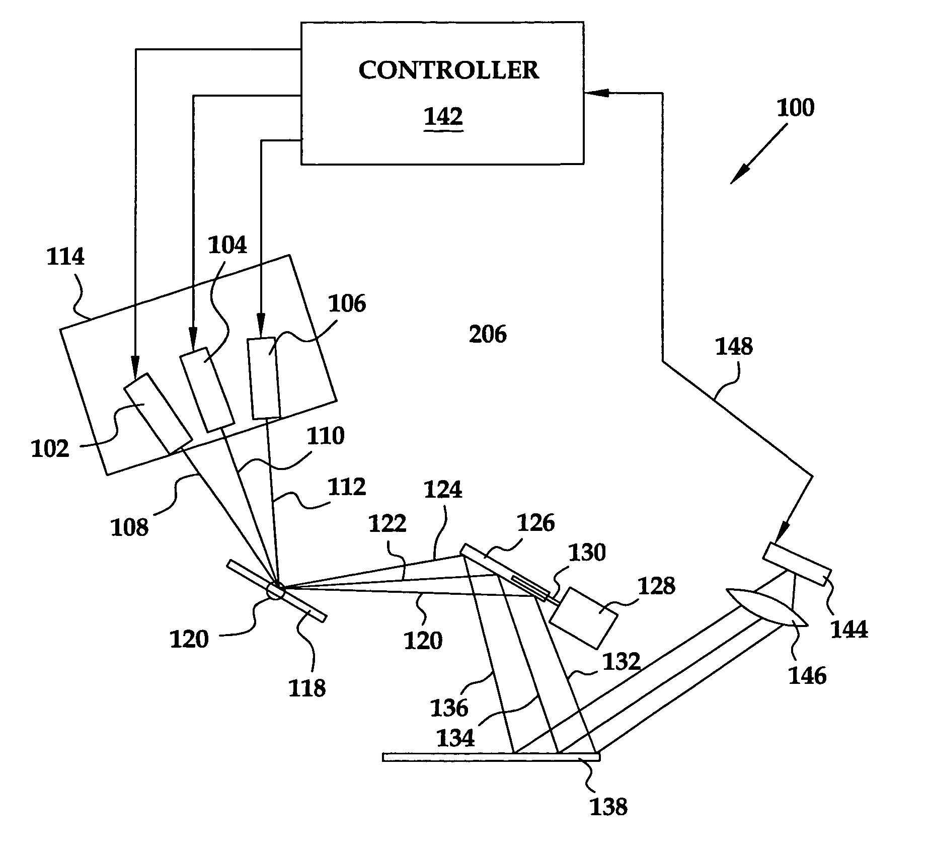
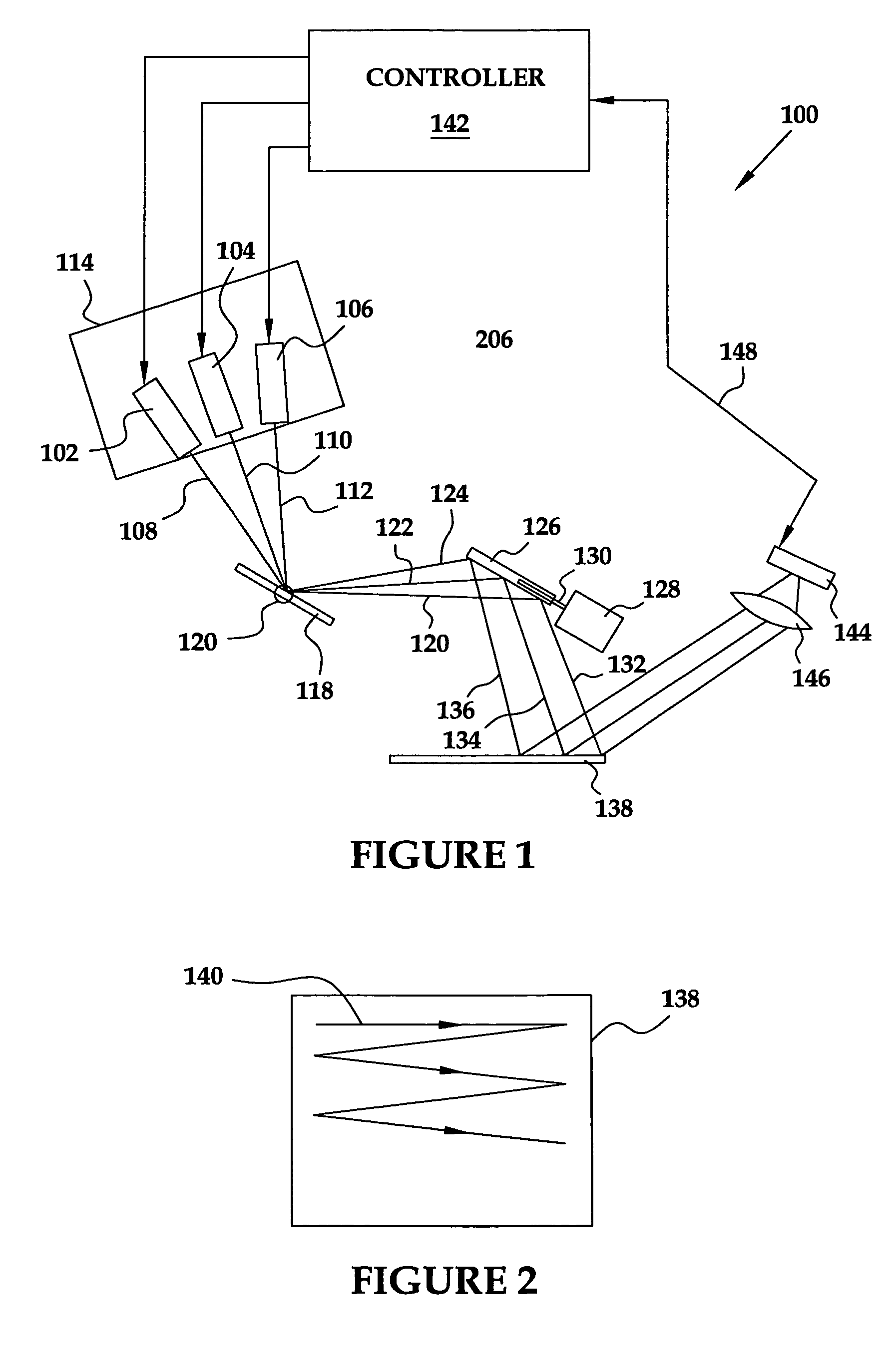
A method and apparatus are provided for controlling the operation of a Laser Projection Display (LPD). Generally, the LPD is comprised of a laser, an optical system and a controller. The laser is adapted to emit a beam of laser light. The optical system is adapted to scan the beam of laser light on a display surface in a two-dimensional raster pattern. The controller is adapted to control the rate at which the laser beam is scanned to produce regions of varying resolution on the display surface. The controller is also adapted to present laser light onto the display surface within only selected portions of the two-dimensional raster scan pattern so that spaced apart image regions may be created.

Description

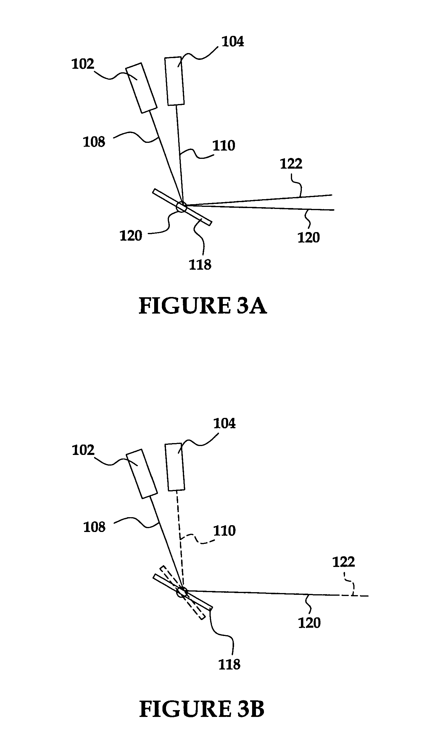
BACKGROUND OF THE INVENTION [0001] 1. Field of the Invention [0002] This invention relates generally to electronic displays, and, more particularly, to a Laser Projection Display (LPD). [0003] 2. Description of the Related Art [0004] A wide variety of electronic devices are available on the market today. Many of these devices interface with consumers visually. That is, many consumer electronic devices, such as desktop computers laptop, computers, notebooks, televisions, Personal Digital Assistants (PDAs), radios, MP3 players, automobile dashboards, cellular telephones, watches, audio equipment, etc. present information to a consumer via a display screen. These display screens may take a wide variety of forms, including Cathode Ray Tubes (CRTs), Liquid Crystal Displays (LCDs), plasma displays, Light Emitting Diodes (LEDs), projectors, and the like. [0005] Generally, these displays have a uniform continuous shape, usually rectangular, and heretofore their shape has not been readily ad...

Claims


Application Information

Patent Timeline
IPC IPC(8): G02B26/10G03B21/00H04N9/31H04N17/00
CPCH04N9/3129
Inventor GOLDMAN, RONDVORKIS, PAULKATZ, JOSEPHNAMBUDIRI, NARAYANSTERN, MIKLOSTAN, CHINHWITTENBERG, CARLWOOD, FREDERICK F.YAVID, DMITRY
Owner MICROVISION
Learn More