In-plane switching mode liquid crystal display device having multi-domains

a liquid crystal display and multi-domain technology, applied in the direction of identification means, instruments, optics, etc., can solve the problems of narrow viewing angle, color shift along the viewing angle, image quality deterioration, etc., to prevent color shift and improve viewing angl

Active Publication Date: 2005-06-30
LG DISPLAY CO LTD
View PDF3 Cites 48 Cited by
  • Summary
  • Abstract
  • Description
  • Claims
  • Application Information

AI Technical Summary

Benefits of technology

[0015] An advantage of the present invention is to provide an in-plane switching mode liquid crystal display device having multi-domain to improve viewing angle and prevent color shift.
[0016] Additional features and advantages of the invention will be set forth in the description which follows, and in part will be apparent from the description, or may be learned by practice of the invention. These and other advantages of the invention will be realized and attained by the structure particularly pointed out in the written description and claims thereof, as well as the appended drawings.
[0017] To achieve these advantages, the IPS mode liquid crystal display device comprises a plurality of pixels defined by a plurality of gate lines and data lines on the first substrate, the pixels including a first region and a second region; a switching member in each pixel; and at least one pair of electrodes disposed substantially parallel in the pixel to form a parallel electric field, the electrodes being bent and symmetric to each other for at least one region of the first and second regions.
[0018] In another aspect of the present invention, an in-plane switching mode liquid crystal display device includes a plurality of gate and data lines defining a plurality of pixels, and at least one pair of electrodes disposed substantially parallel in the pixels, wherein the pixels include at least three domains, wherein a parallel electric field is formed having a different direction for each domain.
[0019] It is to be understood that both the foregoing general description and the following detailed description are exemplary and explanatory and are intended to provide further explanation of the invention as claimed.

Problems solved by technology

Accordingly, there is a problem of a narrow viewing angle when the driving voltage is applied.
In this IPS mode liquid crystal display device, however, there is problem that the color is shifted along the viewing angles.
As a result, the image quality is deteriorated.
In this IPS mode liquid crystal display device having two domains, however, improvement of the viewing angle characteristic may be limited.
When comparing the IPS mode liquid crystal display device having two domains with a cathode ray tube, for example, there are problems that the viewing angle characteristic is low and the color is shifted.

Method used


Image

  • In-plane switching mode liquid crystal display device having multi-domains
  • In-plane switching mode liquid crystal display device having multi-domains
  • In-plane switching mode liquid crystal display device having multi-domains

Examples


first embodiment

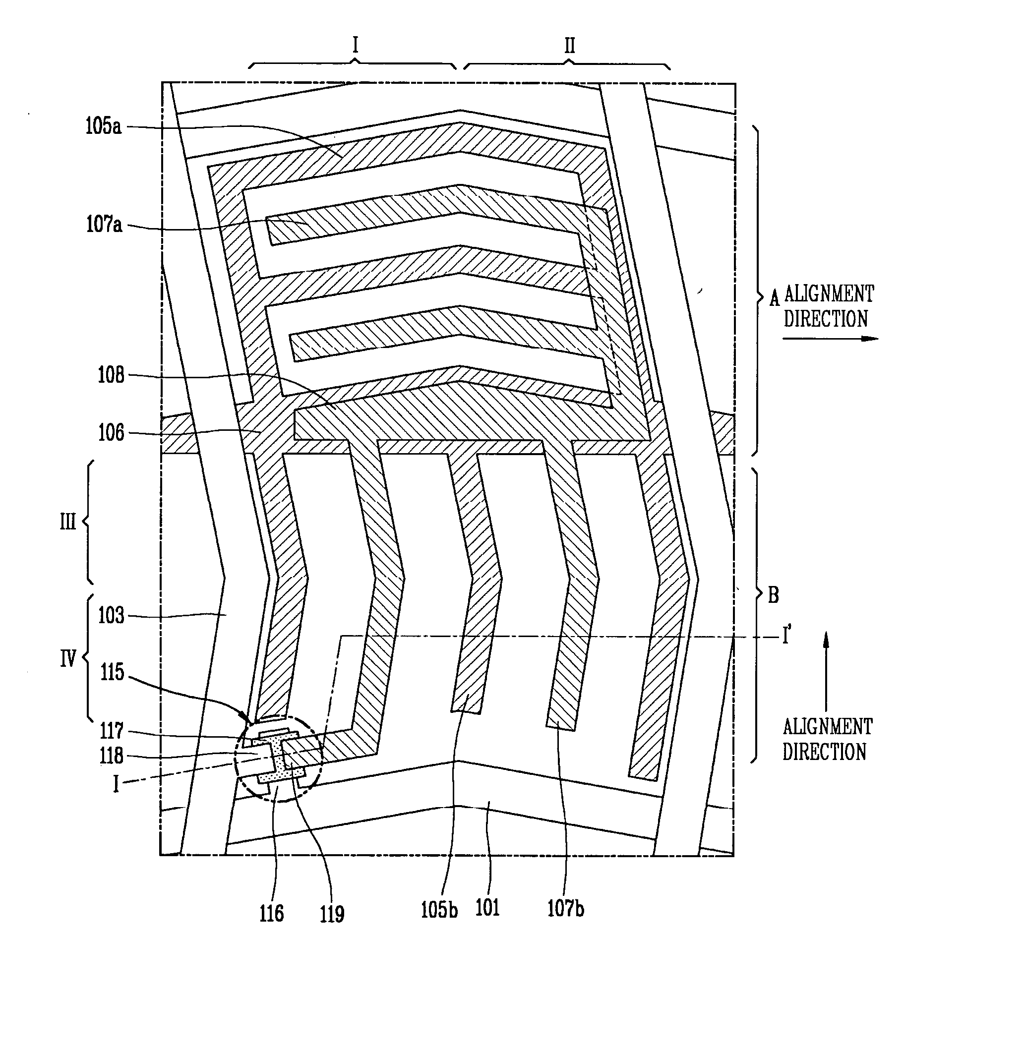
[0030]FIG. 3 is a plan view illustrating the structure of the IPS mode liquid crystal display device according to this invention. At this time, only one pixel will be shown in the drawing for convenience of the description.

[0031] As shown in FIG. 3, the pixel is defined by the gate line 101 and data line 103, and the thin film transistor is disposed within the pixel. The thin film transistor includes a gate electrode 116 connected to the gate line 101 for applying a scan signal thereto, the semiconductor layer 117 over the gate electrode 116 to be activated by the scan signal to form a channel, and the source and drain electrodes 118,119 over the semiconductor layer 117.

[0032] The common electrodes 105a, 105b and the pixel electrodes 107a,107b are disposed in the pixel to form an electric field substantially parallel to the surface of the substrate. The common electrodes 105a, 105b and the pixel electrodes 107a, 107b are respectively connected to the common line 106 and the pixel e...

second embodiment

[0050] In the IPS mode liquid crystal display device of the second embodiment shown in FIG. 6, the pixel includes three-domains. Specifically, the pixel is divided into two regions A, B centering the gate line 201 and the upper region A is also divided into two domains. The common electrode 205a and the pixel electrode 207a are bent at a predetermined angle (for example, 4°-45°) in the upper region A. The common electrode 205a and the pixel electrode 207a are symmetric to each other. In the lower region B, the common electrode 205b and the pixel electrode 207b are arranged along the Y-axis direction (that is, arranged substantially parallel to the data line 203).

[0051] Because the alignment direction in the upper region A is formed in the X-axis direction, the liquid crystal molecules in the first domain I and the second domain II are twisted in an opposing direction when a signal is applied to the pixel electrode 207a. The alignment direction in the lower region B is formed to have...

third embodiment

[0054]FIG. 7 shows the present invention. For the convenience, we will only describe the structure different from the IPS mode liquid crystal display device of other embodiments.

[0055] The structure in FIG. 7 is similar to that of the second embodiment. The pixel includes three domains, that is, an upper region A having two domains and a lower region B. In the upper region A, the common electrode 305a and the pixel electrode 307a, which are respectively symmetric, are bent at an angle of about 5°-45° with respect to the X-axis direction, and the alignment direction is formed in the X-axis direction. The only difference between the third embodiment and the second embodiment are the elongated direction of the common electrode 305b and the pixel electrode 307b, and the alignment direction in the third domain III (i.e., the lower region B). As shown in FIG. 7, the common electrode 305b and the pixel electrode 307b are bent at an angle of about 5°-45° with respect to the Y-axis direction...


PUM

PropertyMeasurementUnit
angleaaaaaaaaaa
electric fieldaaaaaaaaaa
angleaaaaaaaaaa

Abstract

An in-plane switching mode liquid crystal display device having multi domains comprises a plurality of pixels defined by a plurality of gate and data lines on a first substrate each pixel including a first region and a second region, a switching member in each pixel, and at least one pair of electrodes disposed substantially parallel in each respective pixel to form a parallel electric field, the electrodes being bent and symmetric to each other in at least one region of the first and second regions.

Description

[0001] This application claims the benefit of Korean Patent Application No. 2003 / 99376 filed on Dec. 29, 2003 which is hereby incorporated by reference for all purposes as if fully set forth herein. BACKGROUND OF THE INVENTION [0002] 1. Field of the Invention [0003] The present invention relates to an in-plane switching mode liquid crystal display (LCD) device. More particularly, the present invention relates to an in-plane switching mode liquid crystal display device in which a pixel is divided into at least three domains to improve the viewing angle and compensate a color shift problem of the device. [0004] 2. Description of the Related Art [0005] Since the introduction of portable electronic devices such as mobile phones, PDAs, and notebook computers, flat panel display devices such as a Plasma Display Panel (PDP), Field Emission Display (FED), Vacuum Fluorescent Display (VFD), and liquid crystal display (LCD) devices have been actively developed. Among the flat panel display dev...

Claims


Application Information

Patent Timeline
Patent Type & Authority Applications(United States)
IPC IPC(8): G02F1/139G02F1/133G02F1/1337G02F1/1343G02F1/1368G09F9/302
CPCG02F2001/133757G02F1/134363G02F1/133757G02F1/1343
Inventor KIM, WOO-HYUN
Owner LG DISPLAY CO LTD
Why Eureka
Try Eureka