Projection illumination system with tunnel integrator and field lens

a projection illumination and integrator technology, applied in waveguides, lighting and heating apparatus, instruments, etc., can solve the problems of reducing adding and the larger diameter lenses, so as to reduce the uniformity of the brightness of the projected image and add to the cost and complexity of the illumination system

Inactive Publication Date: 2005-06-30
3M INNOVATIVE PROPERTIES CO
View PDF28 Cites 2 Cited by
  • Summary
  • Abstract
  • Description
  • Claims
  • Application Information

AI Technical Summary

Benefits of technology

[0007] This permits the amount of light passing through the illumination system to be maximized and maintains uniform image brightness. The diameter, and therefore the cost, of the relay / imager field lenses may thus also be reduced. The present invention may be applied to photographic slide projectors and enlargers, as well as projectors based on electronic imagers.

Problems solved by technology

If the location of the pupil is unfavorable, it is necessary to use larger diameter lenses in the illumination system.
If the larger lenses are not used, vignetting results, which reduces the uniformity of the brightness of the projected image.
Larger diameter lenses add to the cost and complexity of the illumination system.

Method used


Image

  • Projection illumination system with tunnel integrator and field lens
  • Projection illumination system with tunnel integrator and field lens
  • Projection illumination system with tunnel integrator and field lens

Examples


Embodiment Construction

[0021] In general, the present invention is directed to tunnel integrators useful for uniformizing the illumination of the image in projection systems.

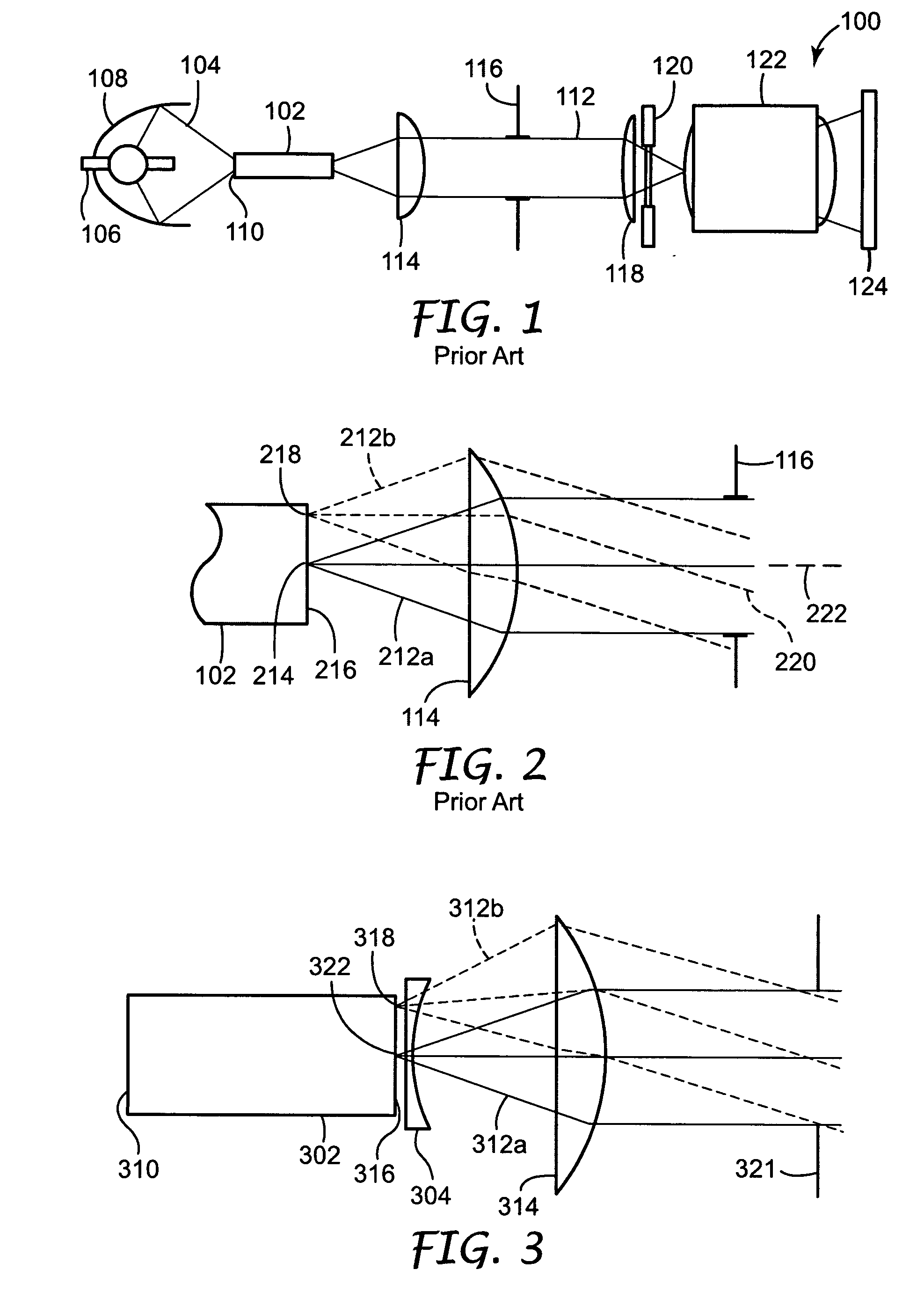
[0022] A prior art illumination system 100 incorporating a tunnel integrator 102 is shown schematically in FIG. 1. Light 104 from the lamp 106 is focused by an elliptical reflector 108 into the input end 110 of the tunnel integrator 102. The light 112 exiting the tunnel integrator 102 is collimated by a condensing lens 114, also referred to as a relay lens, and then passes through an aperture stop 116. The light then passes through the imager field lens 118, the transmissive imager 120 and the projection lens 122 to a screen 124.

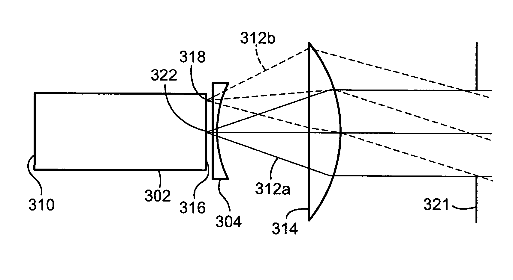
[0023] The transmission of light from the end of the tunnel integrator 102 is more clearly shown in the schematic illustration of FIG. 2. Light rays 212 exit the tunnel integrator 102, to be collimated by the lens 114 and proceed towards the aperture stop 116 of the illumination system 100. Substantially all...


PUM


Abstract

A projector illumination system includes a tunnel integrator incorporated with a field lens at its output end. One advantage of using the field lens is to form an image of the entrance end of the tunnel integrator at the secondary stop of the illumination system when combined with other relay and / or imager field lenses in the illumination system. This reduces vignetting, resulting in an increased uniformity of illumination, and increased light throughput.

Description

RELATED APPLICATION [0001] This application is a continuation of U.S. Ser. No. 10 / 412021 filed on Apr. 13, 2003, the entire disclosure of which is incorporated by reference in its entirety herein.FIELD OF THE INVENTION [0002] The present invention relates in general to illumination systems for projectors, and more particularly to illumination systems for projectors incorporating tunnel integrators. BACKGROUND [0003] Projection systems, for projecting an image on to a screen, use several different components for providing efficient illumination of an imager. Projection systems typically use a lamp generate the illumination light, with several optical elements being interposed between the lamp and the imager to transfer the light to the imager. An imager is an article that impresses an image on a beam of light. It may perform this function through different mechanisms, for example by absorption, as with a photographic slide, by polarization, as with a liquid crystal display (LCD), or ...

Claims


Application Information

Patent Timeline
Patent Type & Authority Applications(United States)
IPC IPC(8): G03B21/00G03B21/14H04N9/31
CPCH04N9/3105Y10S385/901H04N9/3197H04N9/315G03B21/14H04N9/31G03B21/00
Inventor ECKHARDT, STEPHEN K.
Owner 3M INNOVATIVE PROPERTIES CO
Why Eureka
Try Eureka