Plasmonic lens having a surface pattern providing linear-polarization-independent plasmonic focusing and circular polarization dependent plasmonic focusing

a plasmonic lens and surface pattern technology, applied in the field of plasmonic lenses, can solve problems such as common efficiency problems of known designs, and achieve the effects of improving focusing effect, reducing detector size, and reducing focal spot siz

Active Publication Date: 2018-03-20
TECHNION RES & DEV FOUND LTD
View PDF1 Cites 1 Cited by
  • Summary
  • Abstract
  • Description
  • Claims
  • Application Information

AI Technical Summary

Benefits of technology

[0016]Yet another efficiency related problem is associated with the equal amount of SPPs' power propagating inwards and outwards from the boundaries. This reduces the efficiency by additional factor of 2.
[0018]Thus, there is a need in the art in a novel configuration of a plasmonic lens providing desirably high signal-to-noise of the focusing effect and desirable efficiency. The latter is actually defined by two factors, one being associated with maximizing the amount of light coupled into the excited SPPs and the ability to concentrate all this power into a single, constructive focal spot.
[0022]The plasmonic lens of the invention provides for achieving high contrast circular dichroism inside a large area. This allows seamless integration of the plasmonic lens with actual detectors. The out-of-plane field components are desirable in various devices, for example satisfying the absorption selection rules of unipolar quantum wells based detectors. The plasmonic lens of the invention in combination with these detectors may serve as a circular polarization discriminating pixel. It should, however, be understood that the plasmonic lens of the invention may advantageously be used with any type detector.
[0026]It should be understood that due to the improved focusing effect, i.e. reduced focal spot size, the plasmonic lens of the invention provides for reduced detector size, thus potentially improving noise figures related to the volume of the detector.

Problems solved by technology

However, the known designs share common efficiency problems.
Focusing of the out-of-plane field component means generating constructive interference of this field component at the focal point on the metal-dielectric interface.

Method used


Image

  • Plasmonic lens having a surface pattern providing linear-polarization-independent plasmonic focusing and circular polarization dependent plasmonic focusing
  • Plasmonic lens having a surface pattern providing linear-polarization-independent plasmonic focusing and circular polarization dependent plasmonic focusing
  • Plasmonic lens having a surface pattern providing linear-polarization-independent plasmonic focusing and circular polarization dependent plasmonic focusing

Examples


Embodiment Construction

[0036]In order to better understand the subject matter that is disclosed herein and to exemplify how it may be carried out in practice, embodiments will now be described, by way of non-limiting examples only, with reference to the accompanying drawings, in which:

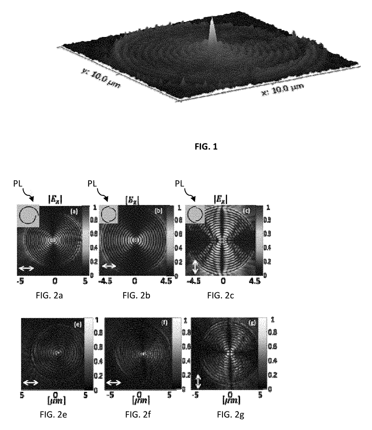
[0037]FIGS. 2a,b,c,e,f,g illustrate the operation of plasmonic lenses of spiral configuration (FIGS. 2a,e) and half circles configuration (FIGS. 2b,c,f,g). As described above, the spiral-shaped plasmonic lenses are incapable of providing sufficient focusing effect (they suffer from blur of the focal spot), while the lens of the half-circles configuration, although solving such spot-size problem, is capable of providing desired focusing only for one of the two linear polarizations of input illumination.

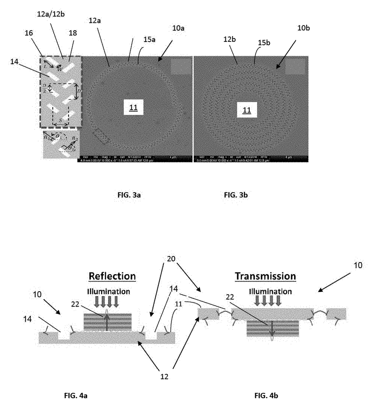
[0038]Reference is made to FIGS. 3a,b showing two examples of a plasmonic lens of the invention. Here, FIG. 3a is a SEM image of a single armed lens 10a, and FIG. 3b is a SEM image of 5 armed lens 10b. More specifically, as sho...


PUM


Abstract

A plasmonic lens is presented comprising a surface for interaction with an input electromagnetic field, wherein this surface has a pattern comprising an arrangement of a plurality of elongated spaced-apart features of a predetermined geometry arranged in a spaced-apart relationship along at least one segment of a spiral curve, each of the pattern features defining an elongated interface for creation of surface waves in response to the interaction with the incident electromagnetic field, such that the pattern provides linear-polarization-independent plasmonic focusing and large area, high contrast, circular polarization dichroic plasmonic focusing.

Description

[0001]This Application claims priority to U.S. Provisional Patent Application Ser. No. 62 / 099,685 filed Jan. 5, 2015.TECHNOLOGICAL FIELD AND BACKGROUND[0002]The present invention relates to plasmonic lenses and their use in imaging systems.[0003]A plasmonic lens is a lens that directs surface plasmon polaritons (SPPs) to converge towards a single focal point. SPPs are surface waves that arise at metal-dielectric interfaces when an electromagnetic field oscillates in unison with free electrons at the surface of the metallic interface constituent.[0004]SPPs can be generated, for instance, by interaction of laser light at a given wavelength (excitation illumination) with corrugations created on metallic surfaces. These waves are confined to the interface and have a wavelength that is much smaller than the wavelength of the excitation illumination at the same frequency. The SPP has electric field components that lie both in and out of the interface plane. The out-of-plane component insi...

Claims


Application Information

Patent Timeline
Patent Type & Authority Patents(United States)
IPC IPC(8): G02B5/00G01J1/04
CPCG01J1/0411G02B5/008G02B1/002
Inventor ORENSTEIN, MEIRSPEKTOR, GRISHA
Owner TECHNION RES & DEV FOUND LTD
Why Eureka
Try Eureka