LCD device and method of driving the LCD device
a technology of lcd device and lcd device, which is applied in the direction of instruments, non-linear optics, lighting and heating apparatus, etc., can solve the problems of lamp malfunction or simply born out at the end of the lamp's life, heavy weight and bulk of crt, and disadvantages of lcd device color realization ratio and luminance ability
- Summary
- Abstract
- Description
- Claims
- Application Information
AI Technical Summary
Benefits of technology
Problems solved by technology
Method used
Image

Examples
first embodiment
[0064] A backlight unit according to the first embodiment of the present invention will be described as follows.
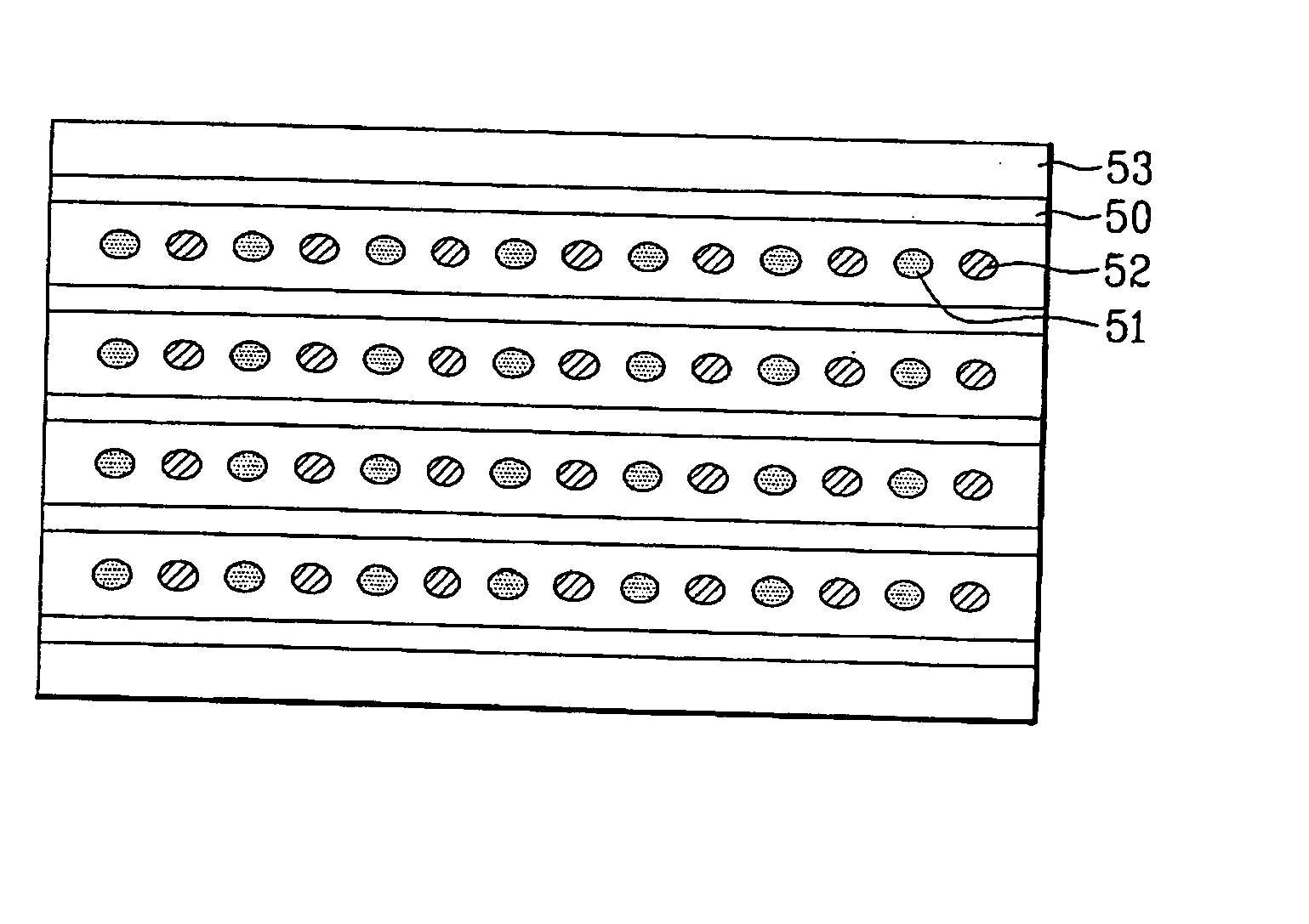
[0065]FIG. 5 is a plane view of a backlight unit, according to the first embodiment of the present invention. As shown in FIG. 5, the backlight unit, according to the first embodiment of the present invention, includes a plurality of fluorescent lamps 50 and a plurality of first and second point light sources 51 and 52 fixed to a case. The lamps 50 and light sources 51 and 52 are under an LCD panel and would constitute a direct type backlight. The plurality of fluorescent lamps 50 are disposed at fixed intervals within the case. The plurality of first and second point light sources 51 and 52 are disposed between the fluorescent lamps 50 and extend in a direction paralleling the fluorescent lamps 50 and alternate with each other.
[0066] Each fluorescent lamp 50 may be a CCFL (Cold Cathode Fluorescent Lamp) of white light having R, G and B wavelengths, a HCFL (Hot Cathode F...
second embodiment
[0068] A backlight unit, according to the second embodiment of the present invention will be described as follows.
[0069]FIG. 6 is a plane view of a backlight unit, according to the second embodiment of the present invention. As shown in FIG. 6, the backlight unit, according to the second embodiment of the present invention, includes a plurality of fluorescent lamps 60 under an LCD panel (not shown), a plurality of first pairs of first and second point light sources 61 and 62 at one side of the LCD panel, and a plurality of second pairs of first and second point light sources 61 and 62 at other side of the LCD panel. The plurality of fluorescent lamps 60 are disposed at fixed intervals to form a direct type backlight unit. The plurality of first and second pairs of first and second light sources 61 and 62 are provided at both ends of the fluorescent lamps 60, wherein each pair of first and second light sources 61 and 62 is provided between the adjacent fluorescent lamps 50.
[0070] E...
third embodiment
[0074] A backlight unit, according to the third embodiment of the present invention, will be described as follows.
[0075]FIG. 7 is a plane view of a backlight unit, according to the third embodiment of the present invention. As shown in FIG. 7, the backlight unit, according to the third embodiment of the present invention, includes a rectangular light-guiding plate 70, first and second fluorescent lamps 71 and 72, and a plurality of first and second point light sources 73 and 74. The first and second fluorescent lamps 71 and 72 are provided at first and second opposite sides of the light-guiding plate 70. The plurality of first and second point light sources 73 and 74 are alternately provided in first and second columns located along third and fourth sides of the light-guiding plate 70.
[0076] Each fluorescent lamps 71 and 72 may be a CCFL (Cold Cathode Fluorescent Lamp) of white light having R, G and B wavelengths, a HCFL (Hot Cathode Fluorescent Lamp), or an EEFL (External Electro...
PUM
 Abstract
Description
Claims
Application Information
 - R&D Engineer
- R&D Manager
- IP Professional
- Industry Leading Data Capabilities
- Powerful AI technology
- Patent DNA Extraction
Browse by: Latest US Patents, China's latest patents, Technical Efficacy Thesaurus, Application Domain, Technology Topic.
© 2024 PatSnap. All rights reserved.Legal|Privacy policy|Modern Slavery Act Transparency Statement|Sitemap