Modular lighting bar

a module and lighting bar technology, applied in the field of electric lighting, can solve the problems of inability to manufacture, prohibitively expensive standardization and mass marketing, and the inability to install conventional railing systems,

Inactive Publication Date: 2005-06-30
SUNCOR STAINLESS
View PDF31 Cites 95 Cited by
  • Summary
  • Abstract
  • Description
  • Claims
  • Application Information

AI Technical Summary

Benefits of technology

[0017] In yet another embodiment, the modular lighting bar may additionally be used to hold rods and tubes such as, for example, railing balusters in both horizontal and vertically sloping railing configurations. In such configurations, substantially identical top and bottom lighting bars additionally have a series of recesses suitably shaped to securely hold solid bars or hollow tubing that form railing balusters or spindles. The electrical supply line recess is offset from the baluster-holding recesses to prevent interference between the low voltage installation and any metal surface of the balusters.
[0018] In order to accommodate sloping staircase railings, the lighting bars may additionally be configured with a plurality of rotating pl...

Problems solved by technology

Average homeowners, and even semi-skilled construction workers, find conventional railing systems nearly impossible to install.
Specialized installation knowledge and the present need for a variety of fittings have made standardization prohibitively expensive and mass marketing infeasible.
These problems are compounded when in railings installations on staircases such as, for example, on decks where electrical lighting is also desirable.
There are too many variables to make existing systems easy to install, as there are a wide variety of fittings from which selections can be...

Method used


Image

  • Modular lighting bar
  • Modular lighting bar
  • Modular lighting bar

Examples


Embodiment Construction

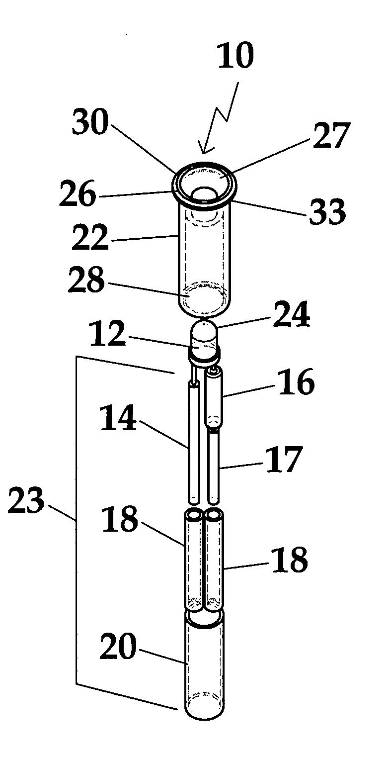
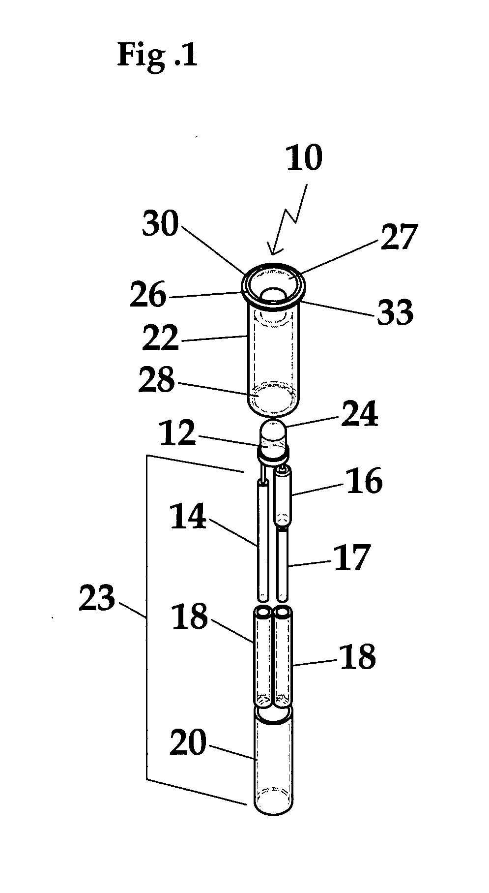
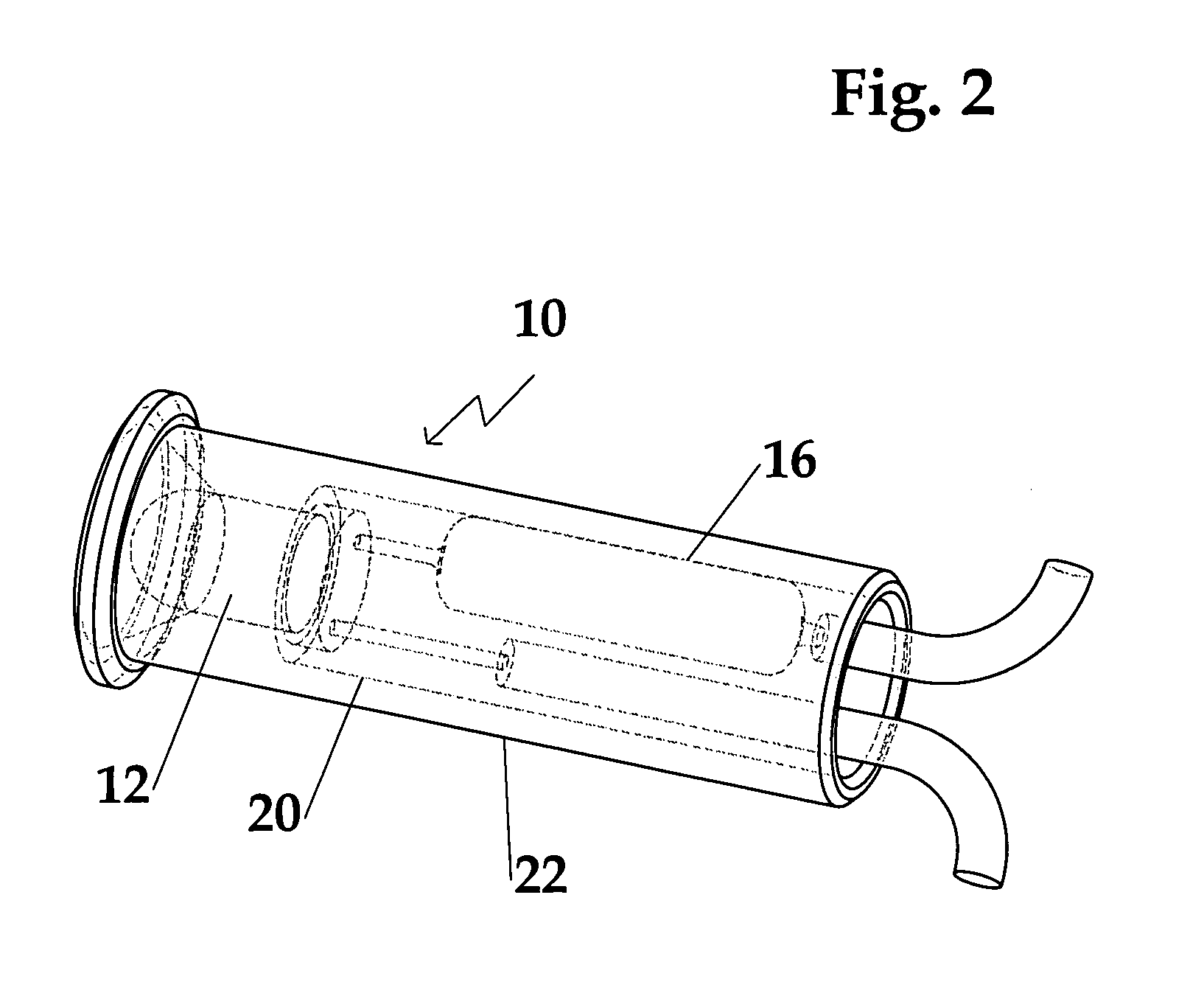
[0040] With reference to FIGS. 1 and 2, a non-limiting example of miniature light assemblies 10 that may be employed in the lighting bar of the present invention includes a bright LED 12, an electric insulated wire having a negative lead 14 connected to the LED 12, a resistor 16 connected to the LED 12, and an electric insulated wire having a positive lead 17 connected to the resistor 16. Note that the wires are preferably insulated, specifically to allow use of metal components, but if the components of the lighting bar are formed of a non-conductive material such as plastic the need to insulation disappears. The term “wire” as used herein refers to a conductive material having sufficient strength and rigidity to puncture the plastic coatings found on conventional electrical supply lines. The portion of the wires protruding from the housing are referred to interchangeably below as ‘prongs’ or ‘leads’, and they may include tapered or beveled ends to facilitate the puncturing of the ...


PUM


Abstract

Modular lighting bar mountable on a surface into which may be mounted one or more miniature light sources and an electrical supply line. The light sources can include light emitting diodes. The lighting bar has alternative single and two-component configurations that fix the position of the electrical supply line, and may be formed with a recess that receives an asymmetrically shaped electrical supply line in only one possible orientation. The ends of the lighting bar include mateable features for connecting additional bars. The bars may include recesses for receiving rigid members such as railing balusters, and optionally rotatable plugs to allow adaptation of the mounting bars to fit stair case railings with lighting and/or balusters.

Description

CROSS REFERENCE TO RELATED PATENT APPLICATIONS [0001] This application is a continuation-in-part of co-pending U.S. patent application Ser. No. 10 / 755,516 entitled “Super Bright LED Utility And Emergency Light”, filed Jan. 12, 2004, which is a continuation-in-part of co-pending U.S. patent application Ser. No. 09 / 968,560 filed Oct. 1, 2001, which claims priority of U.S. Provisional Application Ser. No. 60 / 237,012 entitled “Super Bright LED Utility And Emergency Light”, filed Sep. 29, 2000, all of the above are herein incorporated by reference in their entirety.FIELD OF THE INVENTION [0002] The present invention relates generally to electrical lighting and, more particularly, to easily installed recessed lighting for use with railings and similar structures. BACKGROUND OF THE INVENTION [0003] Average homeowners, and even semi-skilled construction workers, find conventional railing systems nearly impossible to install. Specialized installation knowledge and the present need for a vari...

Claims


Application Information

Patent Timeline
IPC IPC(8): E04F11/18F21K99/00F21V21/28F21V23/04F21Y101/02
CPCE04F2011/1048E04F2011/1872F21S4/008F21S9/022F21S9/03F21Y2101/02F21V23/0442F21V31/005F21V33/006F21W2111/027F21W2111/08F21V21/28F21S4/28F21Y2115/10
Inventor STRIEBEL, ROMAN F.
Owner SUNCOR STAINLESS
Why Eureka
Try Eureka