Setting device of distributed energy supply system

a technology of distributed energy supply and device, applied in the direction of electric devices, fuel energy technology, instruments, etc., can solve the problems of no economic advantage, cost required, no economic advantage of fuel cell operation,

Inactive Publication Date: 2005-06-30
PANASONIC CORP
View PDF3 Cites 19 Cited by
  • Summary
  • Abstract
  • Description
  • Claims
  • Application Information

AI Technical Summary

Benefits of technology

[0017] It is an object of the present invention to provide an apparatus of setting dispersed energy supplying system which, taking into account the aforementioned problems, performs assessment of economical efficiency of energy supplied from the exterior and allows ordinary users to select assessment for environmental protection, on the basis of which judgment of optimum operating method or system design can be made. It is another object of the present invention to allow the assessment of economical efficiency to reflect the change of rate system of energy with time zone if any.
[0018] It is a further object of the present invention to provide an apparatus of setting a dispersed energy supplying system which can take into account both economical efficiency and environmental protection by automatically realizing judgment of optimum operation schedule or system design even if ordinary users do not make judgment by themselves.
[0072] Further, a twenty eighth invention of the present invention lies in a program of allowing a computer to function as an energy generation cost calculating means of calculating energy generation cost required for the aforementioned energy generating means to generate the aforementioned generated energy suitable for the aforementioned load, an external energy supply cost calculating means of calculating supply cost of the aforementioned external energy suitable for the aforementioned load, an LCA data storage means of storing an environmental burden generated at whole or part of the steps of producing, operating and discarding the aforementioned energy generating means as a first life cycle assessment (LCA) data and an environmental burden generated at whole or part of the steps of producing, operating and discarding facilities of supplying the aforementioned external energy as a second LCA data and an interface means of presenting the aforementioned energy generation cost, the aforementioned external energy supply cost and the aforementioned first and second LCA data and allowing the user to set the aforementioned energy generating means and / or the aforementioned external energy supplying means in an apparatus of setting a distributed energy supplying system of the first invention of the present invention.

Problems solved by technology

Incidentally, the operation of a fuel cell has no economic advantage unless the unit cost of electric power generated by the fuel cell, i.e., the cost of a fuel gas required for the fuel cell to generate a unit amount of electric power is lower than the cost required to buy commercial electric power from an electric power company, etc.
Accordingly, even if a fuel cell is operated in a time zone having a low unit rate of electric power as in the midnight, there is no economical advantage.
To date, however, the supply of an energy such as electric power and gas has never been considered taking into account such an environmental protection.
Further, data on systematic rate of energy such as electricity and gas on the basis of which economical efficiency is evaluated, particularly real time data concerning the cost changing every hour is difficultly available.
Accordingly, it has been difficult to control the operation of a dispersed energy supplying system such as fuel cell system and even build and design such a system according to these data.

Method used


Image

  • Setting device of distributed energy supply system
  • Setting device of distributed energy supply system
  • Setting device of distributed energy supply system

Examples


first embodiment

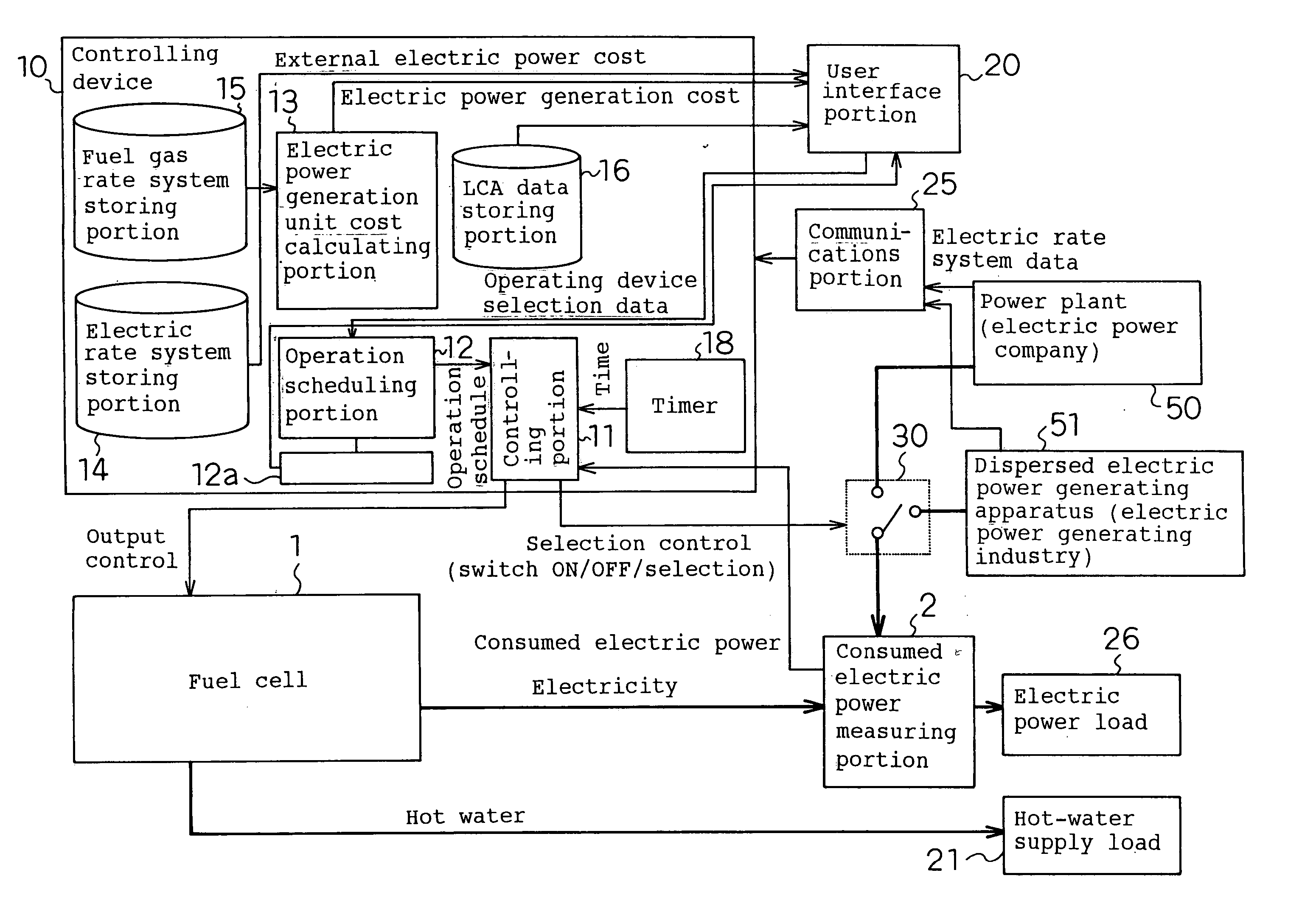
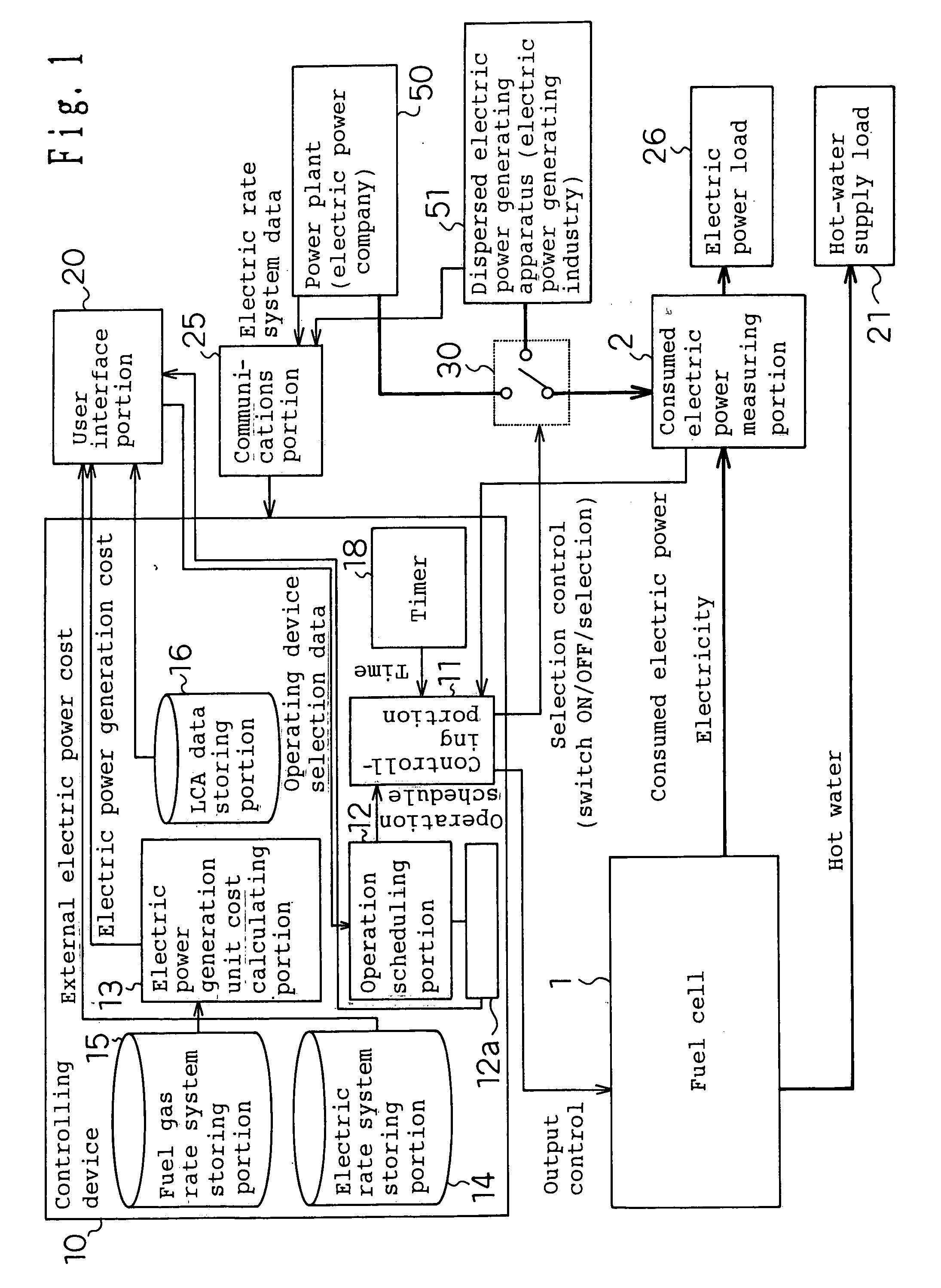
[0112]FIG. 1 is a constitutional diagram illustrating a configuration of a fuel cell system according to the first embodiment of implementation of the present invention and a controlling device therefor. In FIG. 1, the reference numeral 1 indicates a fuel cell and the reference numeral 2 indicates an electric power consumption measuring portion comprising an electric power sensor for measuring the electric power consumption of the electric power load 26 incorporated therein. The reference numeral 30 indicates a switch required to use the power plant 50 as an external electric supply or use electricity from the dispersed electric power generating apparatus 51. The power plant 50 means an electric power company or the like and the dispersed electric power generating apparatus 51 means other electric power generating industry, i.e., industry that supplies and sells commercial electric power. The reference numeral 21 is a hot-water supply load that utilizes heat outputted by the fuel ce...

second embodiment

of Implementation of the Invention

[0173]FIG. 4 is a constitutional diagram illustrating a configuration of the controlling device according to the second embodiment of implementation of the present invention. In FIG. 4, where the parts are the same as or correspond to those of FIG. 1, the same reference numerals are used and their detailed description will be omitted. Further, the reference numeral 100 indicates an internet service provider (ISP) which operates to provide data such as electric power rate unit cost in the case where electricity is bought from the power plant 50 of an electric power company or the dispersed electric power generating apparatus 51 of other electric power generating industries and distributes, in addition to these data, an operating method judgment data having an algorithm of forecasting and determining optimum operating method from these data. In the controlling device 10″, the operating method judgment data storing portion 17 is a means of retaining on...

third embodiment

of Implementation of the Invention

[0228]FIG. 11 is a constitutional diagram illustrating a configuration of the controlling device according to the third embodiment of implementation of the present invention. In FIG. 11, where the parts are the same as or correspond to those of FIGS. 1 and 4, the same reference numerals are used and their detailed description will be omitted.

[0229] The present embodiment of implementation of the invention comprises a controlling device 200 and a switch 20, the controlling device 200 not being supplied from the fuel cell or external electric power, and a switch 30 can be supplied with electric power from a fuel cell 210 which can be connected thereto in the future or an electric power industry 220 which can be contracted in the future but is shown having nothing connected thereto at present.

[0230] The internet service provider (ISP) 230 operates to provide data such as electric power rate unit cost charged when electricity is bought from the power ...


PUM

PropertyMeasurementUnit
timeaaaaaaaaaa
energyaaaaaaaaaa
external energyaaaaaaaaaa

Abstract

Heretofore, in a dispersed energy supplying system, the unit cost of energy generated in houses and the unit rate of energy bought from an electric power company, etc. have been compared, but consideration has never been made of environmental burden. There are provided a controlling portion 11 of controlling the operation of a fuel cell, a switch 30 of selectively supplying the electric power of the fuel cell or an external electric power into an electric power load, an electric power generation unit cost calculating portion 13 of calculating the electric power generation cost of the fuel cell, an electric rate system storing portion 14 of calculating the cost of a power plant 50 and a dispersed electric power generating apparatus 51, an LCA data storing portion 16 of storing LCA data of the fuel cell, the power plant 50 and the dispersed electric power generating apparatus 51, and a user interface portion 20 of presenting electric power generation cost, external electric power cost and LCA data and allowing the user to determine the controlling operation of the aforementioned controlling portion 11 and / or the selecting operation of the switch 11.

Description

TECHNICAL FIELD [0001] The present invention relates to an apparatus of setting a distributed energy supplying system using a means of generating energy from an external energy source such as fuel cell. BACKGROUND ART [0002] A fuel cell is an energy-saving system which undergoes chemical reaction of a fuel gas with air to generate electricity and supplies electric power as well as heat generated during the electricity generation as heat energy. The operation of a fuel cell has heretofore generally involved an electric power load follow-up operation that causes the fuel cell to generate electricity in conformance with the amount of electric power consumed by the electric power load and causes electricity to be bought from commercial power line when the consumed amount of electric power exceeds the rated electric generation of the fuel cell. [0003] When the electricity generation of the fuel cell is converged to the target control value by controlling the supplied amount of fuel gas, ...

Claims


Application Information

Patent Timeline
Patent Type & Authority Applications(United States)
IPC IPC(8): H01M8/04H01M16/00H02J3/00
CPCG06Q50/06H01M8/0494H01M8/04947Y02E60/50H02J3/005H02J2001/004H01M16/003Y02P90/40H02J2300/30Y04S10/50H02J3/0075H02J3/007
Inventor NAGAMITSU, SACHIOMATSUI, MASARUMATSUBAYASHI, SHIGEAKI
Owner PANASONIC CORP
Why Eureka
Try Eureka