Communication network analysis apparatus with internetwork connectivity

a technology of communication network and analysis apparatus, applied in the direction of transmission monitoring, receiver monitoring, television system, etc., can solve the problems of limited data storage amount, network damage or other detrimental phenomena, and few customers cannot receive one or more channels clearly

Inactive Publication Date: 2005-06-30
ACTERNA LLC
View PDF23 Cites 40 Cited by
  • Summary
  • Abstract
  • Description
  • Claims
  • Application Information

AI Technical Summary

Benefits of technology

[0013] A second embodiment of the invention is an apparatus that includes a coupling, a diagnostic circuit, a cable modem circuit, a display and a processing circuit. The coupling is configured to connect to a coaxial cable termination of a communication network, and is operable to receive broadband RF signals. The diagnostic circuit is operably coupled to the coupling to receive at least a first RF signal, and is operable to obtain diagnostic information based on the first RF signal. The cable modem circuit is operably coupled to the coupling to receive at least a second RF signal, and is operable to generate data packets from the second RF signal. The cable modem is further operable to generate an RF transmission signal, the RF transmission signal including transmission data packets. The display has less a five inch diagonal dimension, enabling a portable, handheld device. The processing circuit is connected to the cable modem circuit, and is operable to execute a web browser, the web browser operable to cause the display to display information obtained from the data packets.

Problems solved by technology

Because the cable plant is dispersed throughout the entire cable service area, the network can experience damage or other detrimental phenomena in varied, isolated portions of the network.
As a result, many customers may have excellent service while a few customers cannot receive one or more channels clearly due to a localized problem.
However, there is a limit to the amount of data that may be stored, and the information that a technician may find useful is not always predictable.

Method used


Image

  • Communication network analysis apparatus with internetwork connectivity
  • Communication network analysis apparatus with internetwork connectivity
  • Communication network analysis apparatus with internetwork connectivity

Examples


Embodiment Construction

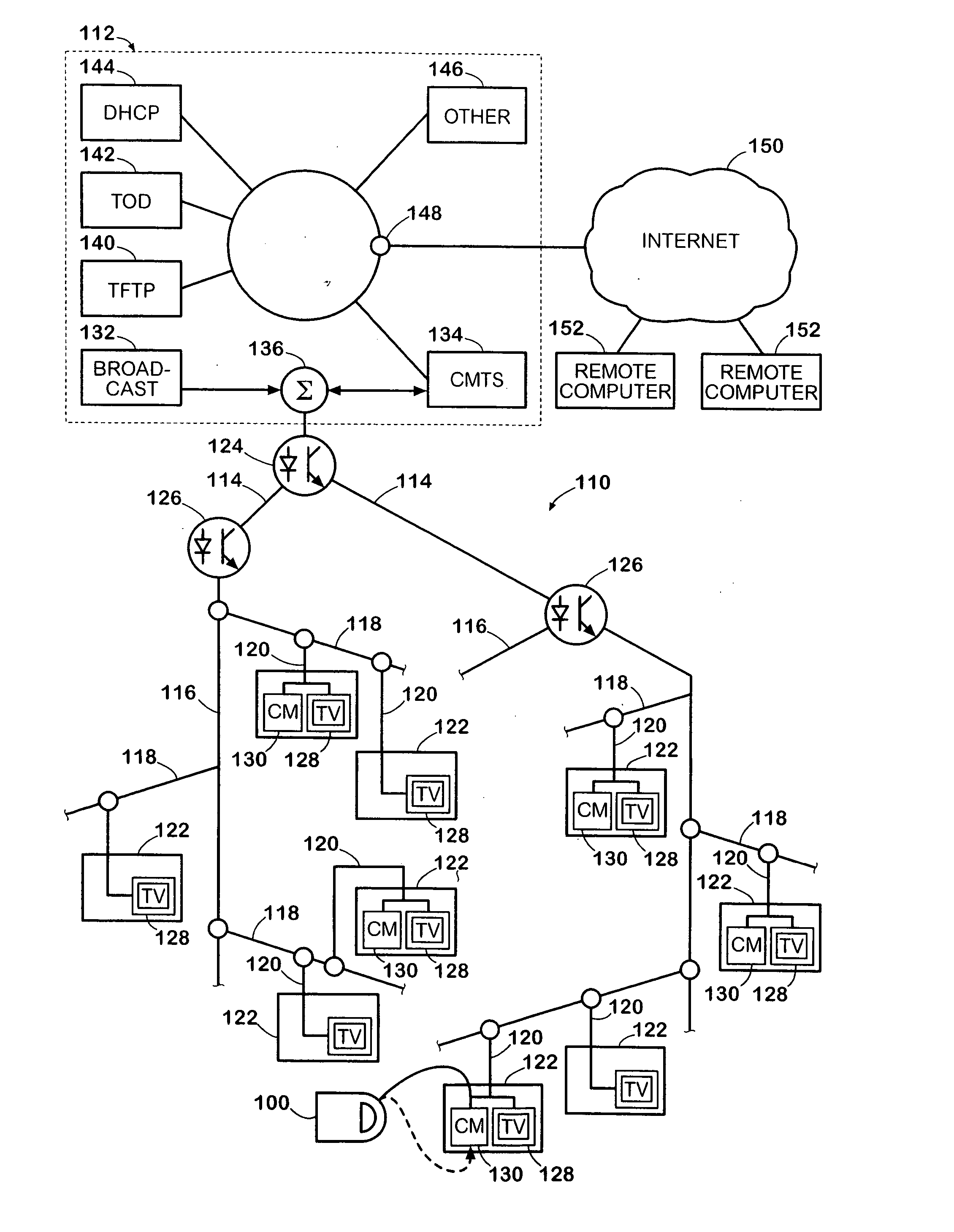
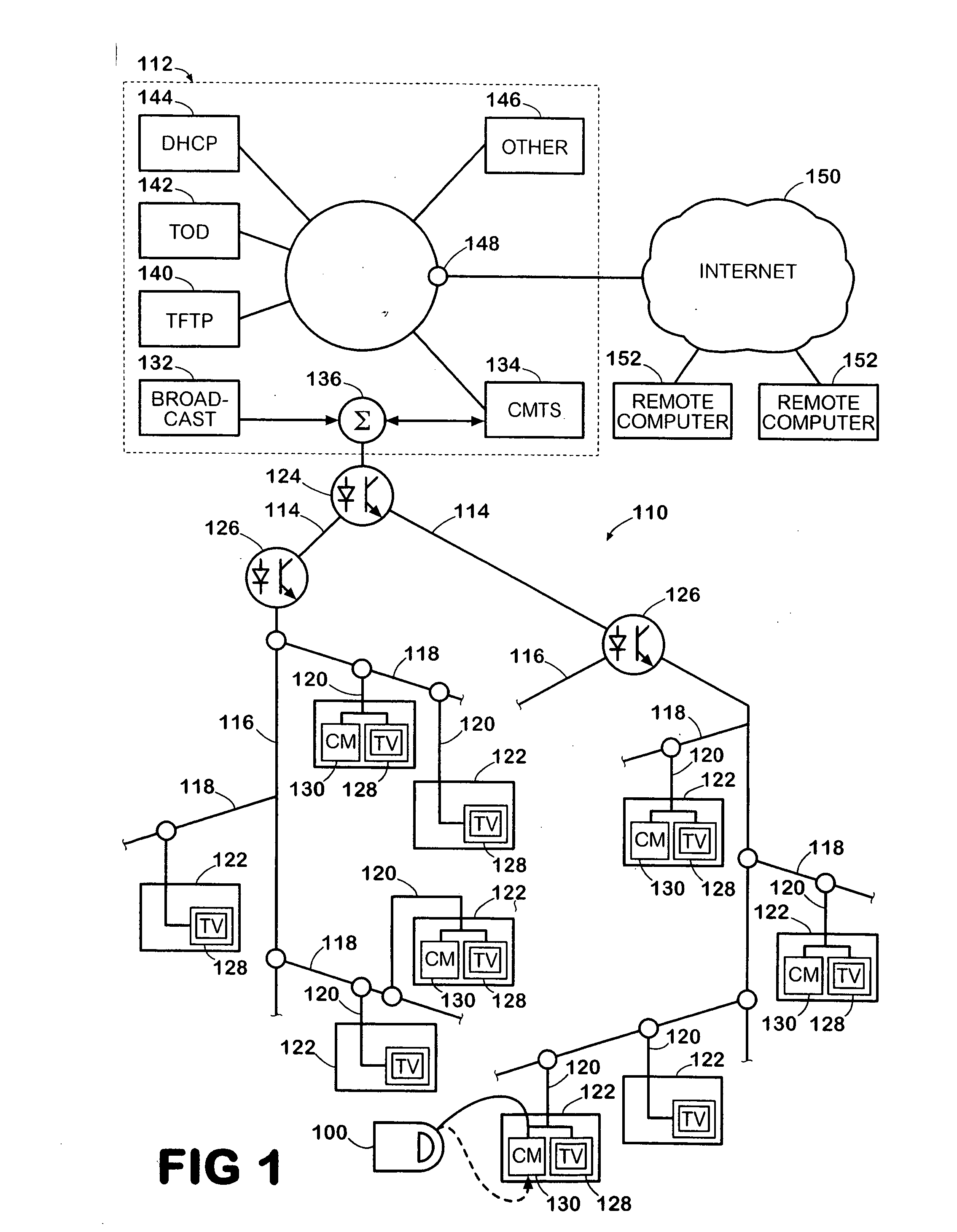
[0026]FIG. 1 shows an exemplary test configuration that employs an analysis device 100 according to the present invention within a communication network 110. The communication network 110 is a land-based broadband network typically known as a cable network. In the embodiment described herein, the communication network 110 is a hybrid fiber coax or HFC network that employs both fiber optic links and coaxial cable to effect radio frequency communications between a plurality of subscribers and a network headend 112. The network headend 112 is further operable to provide Internet communications between a plurality of subscribers and one or more devices 152 connected to the Internet 150. The devices 152 are external to the communication network 110. The analysis device 100 is operable to test multiple parameters of the network, including by way of example, the signal strength at a remote location of the network 110, whether Internet connectivity is available at remote locations of the ne...


PUM


Abstract

An apparatus includes a coupling, a diagnostic circuit, a cable modem circuit, a display, and a processing circuit. The coupling is configured to connect to a coaxial cable termination of a communication network, and is operable to receive broadband RF signals. The diagnostic circuit is operably coupled to the coupling to receive a first RF signal, and is operable to obtain diagnostic information regarding the first RF signal. The cable modem circuit is operably coupled to the coupling to receive a second RF signal, and is operable to generate data packets from the second RF signal. The cable modem is further operable to generate an RF transmission signal, the RF transmission signal including transmission data packets. The processing circuit is connected to the cable modem circuit and is operable to execute a web browser. The web browser is operable to cause the display to display information obtained from the data packets. The processing circuit is further operable to cause display of at least some diagnostic information.

Description

CROSS REFERENCE TO RELATED APPLICATIONS [0001] This application claims the benefit of U.S. Provisional Patent Application Ser. No. 60 / 516,189, filed Oct. 31, 2003, and which is incorporated herein by reference. [0002] Cross-reference is made to co-pending U.S. patent application Ser. No. [Express Mail No. EV505540125US, attorney docket 1504-0075], entitled “Signal Level Measurement and Data Connection Quality Analysis Apparatus and Methods”, filed Nov. 1, 2004, and to co-pending U.S. patent application Ser. No. [Express Mail No. EV505540142US, attorney docket 1504-0085], entitled “Versatile Communication Network Test Apparatus and Methods”, filed Nov. 1, 2004.FIELD OF THE INVENTION [0003] The present invention relates generally to broadband communication networks, and more particularly, to testing and / or analysis of broadband communication networks. BACKGROUND OF THE INVENTION [0004] Cable networks are communication networks that communicate broadband communication signals between a...

Claims


Application Information

Patent Timeline
Patent Type & Authority Applications(United States)
IPC IPC(8): H04B17/00H04N7/173H04N17/00
CPCH04N7/17309H04N17/00H04B17/309H04N21/4782H04B17/23H04N21/4622H04N21/42676H04N21/44209
Inventor GOTWALS, MICHAEL D.FLASK, ROBERT J.
Owner ACTERNA LLC
Why Eureka
Try Eureka