
Flat tube cold plate assembly

Active Publication Date: 2005-07-07
LYTRON
View PDF9 Cites 18 Cited by
  • Summary
  • Abstract
  • Description
  • Claims
  • Application Information

AI Technical Summary

Benefits of technology

[0006] The present invention relates to a cold plate assembly that achieves high heat transfer performance at lower cost. A plurality of flat tubes is arranged along a fluid flow path defined by an opening(s) in a channel plate. The flat tubes and the channel plate form a substantially planar structure that is sandwiched between upper and lower cover plates.

Problems solved by technology

In high power applications, liquid can be used to provide significantly improved cooling, but at an added level of complexity.

Method used


Image

  • Flat tube cold plate assembly
  • Flat tube cold plate assembly
  • Flat tube cold plate assembly

Examples


Embodiment Construction

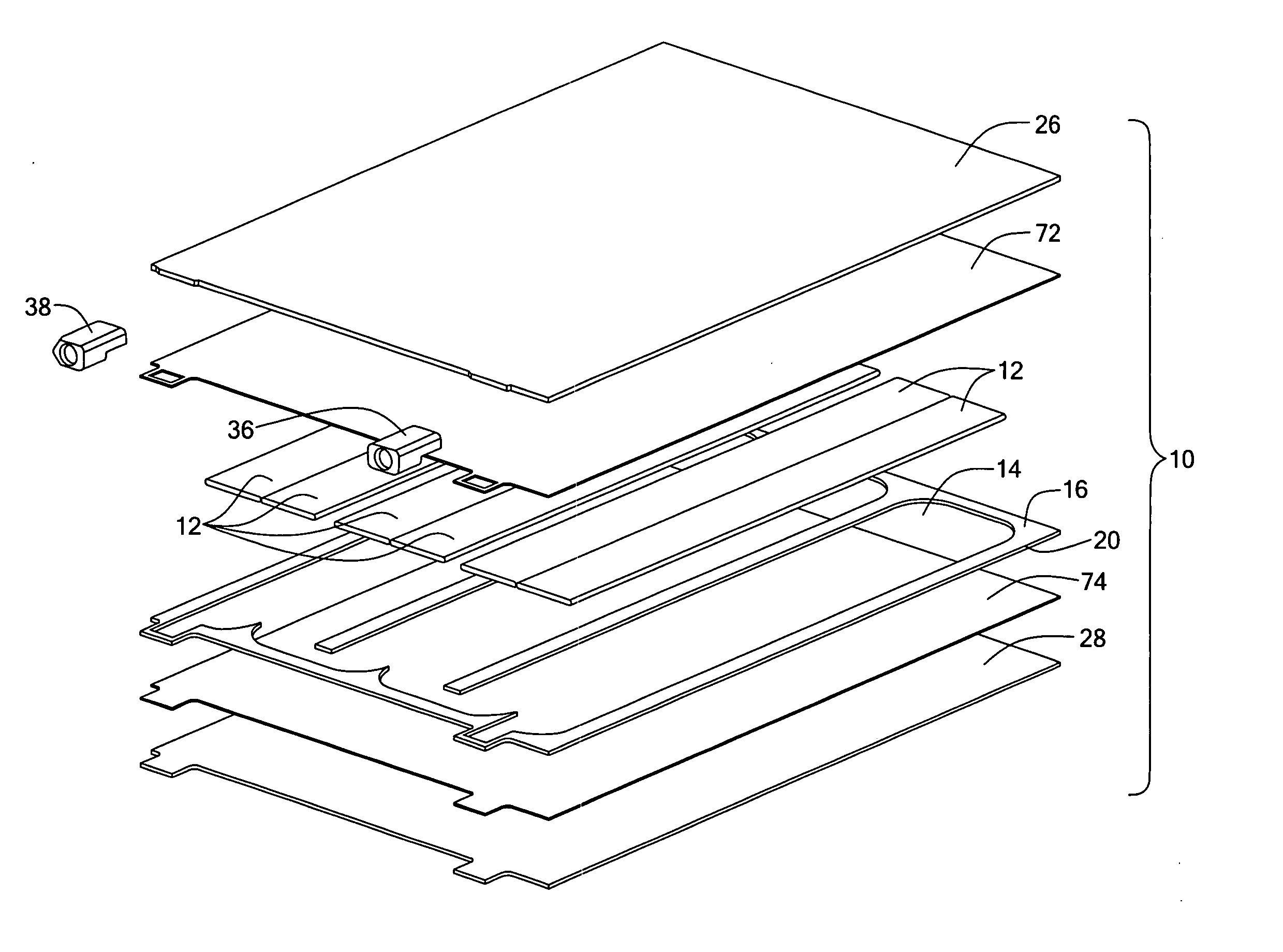
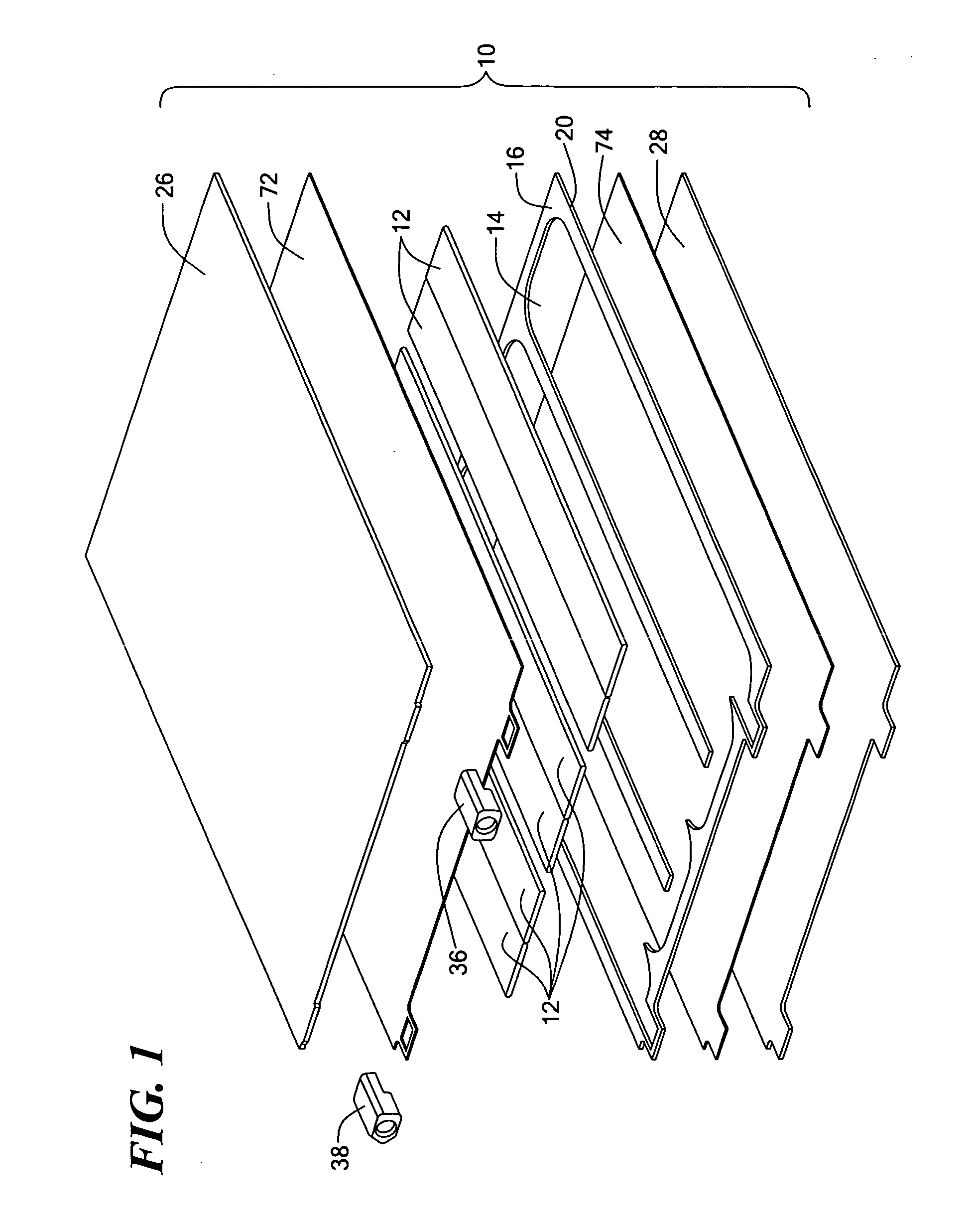
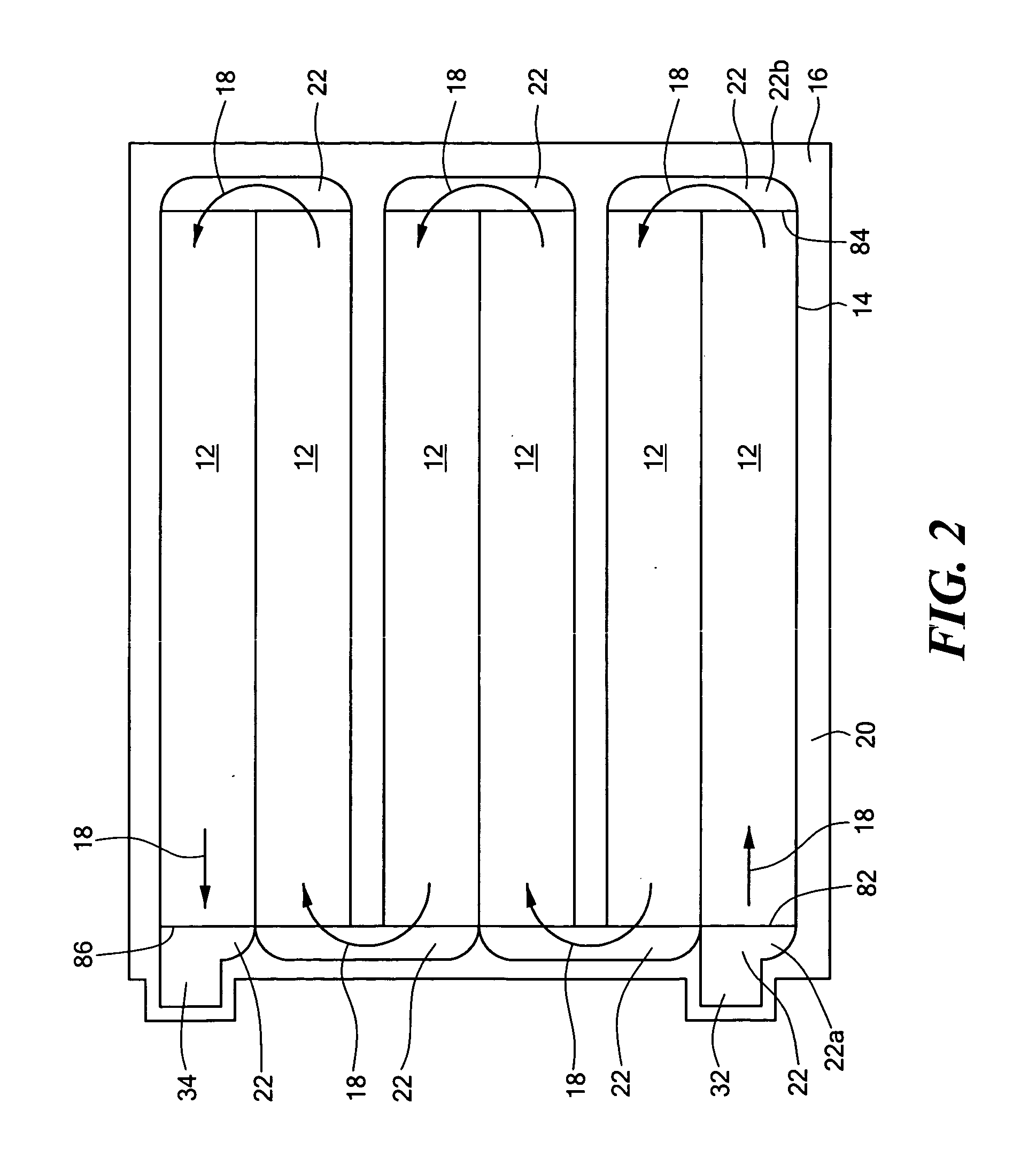
[0014] An embodiment of a flat tube cold plate assembly 10 according to the present invention is illustrated in FIGS. 1-3. A plurality of flat tubes 12 is disposed in an opening(s) 14 in a channel plate 16. The tubes include internal fins, described further below, to aid in the heat transfer. The opening in the channel plate defines a fluid flow path therethrough (indicated by arrows 18 in FIG. 2) for a cooling fluid, and the channel plate provides a frame 20 for retaining the flat tubes on the flow path. The opening in the channel plate also includes regions 22 located at the ends of the flat tubes through which the cooling fluid is directed into and out of the flat tubes. An upper cover plate 26 and a lower cover plate 28 are provided over the flat tubes and the channel plate to retain all the components in an assembly and to seal the flow path. A fluid inlet 32 and a fluid outlet 34 are provided via one or more fittings 36, 38 attached at suitable locations, such as along the edg...


PUM


Abstract

A flat tube cold plate assembly has a channel plate having an opening therethrough defining a flow path. A plurality of flat tubes is retained within the opening in the channel plate along the flow path. A plurality of fins extends within the interior of the flat tube. An upper cover plate and a lower cover plate are fixed over the channel plate with the flat tube disposed therein, for example, by brazing. The flat tube may be readily formed by an extrusion process. The opening in the channel plate may be readily formed by a process such as laser cutting, stamping, or etching.

Description

CROSS REFERENCE TO RELATED APPLICATIONS [0001] This application claims the benefit under 35 U.S.C. §119(e) of U.S. Provisional Application No. 60 / 530,442, filed Dec. 17, 2003, the disclosure of which is incorporated by reference herein.STATEMENT REGARDING FEDERALLY SPONSORED RESEARCH OR DEVELOPMENT [0002] N / A BACKGROUND OF THE INVENTION [0003] Electronic components mounted on circuit boards generate heat that must be dissipated to assure proper functioning of the components. Air is typically used to cool the circuit board when the total power dissipated is low or when the power density is low. In high power applications, liquid can be used to provide significantly improved cooling, but at an added level of complexity. The liquid must be contained so it does not contact the components directly. [0004] A way to contain cooling liquid is to use a liquid-cooled cold plate, typically made of copper, aluminum, or alloys thereof. The cold plate has channels within it that distribute the co...

Claims


Application Information

Patent Timeline
IPC IPC(8): F28F3/12
CPCF28F3/12
Inventor THOMAS, ANDYAKSELBAND, BORISROLLINS, BRIAN
Owner LYTRON
Learn More