Track assembly

a technology of track and assembly, which is applied in the direction of belt/chain/gearing, mechanical equipment, belt/chain/gearing, etc., can solve the problems of not being designed to be converted, not easily removed, and affecting the traction of the vehicle, so as to achieve the effect of effectively lengthening the wheelbase of the vehicle, and increasing traction and stability

Active Publication Date: 2005-07-07
ASV HLDG INC
View PDF10 Cites 48 Cited by
  • Summary
  • Abstract
  • Description
  • Claims
  • Application Information

AI Technical Summary

Benefits of technology

[0021] An advantage of the present invention is that the track assembly can be transferred from one vehicle to another vehicle.
[0022] Another advantage of the invention is that traction and stability are increased by effectively lengthening the wheelbase of a vehicle.
[0023] Another advantage of the invention is that traction and stability are increased by providing the vehicle with an independent front suspension system.
[0024] These and other objectives and advantages of the invention will appear more fully from the following description, made in conjunction with the accompanying drawings wherein like reference characters refer to the same or similar parts throughout the several views. And, although the disclosure hereof is detailed and exact to enable those skilled in the art to practice the invention, the physical embodiments herein disclosed merely exemplify the invention, which may be embodied in other specific structure. While the preferred embodiment has been described, the details may be changed without departing from the invention, which is defined by the claims.

Problems solved by technology

Often, they are used in conditions where the surface upon which they traverse is not capable of supporting the weight of the skid-steer loader and they can become mired and / or lose traction.
A problem with permanent tracked vehicles is that they are not designed to be converted to wheeled vehicles.
A problem with undercarriage systems is that they are also designed with permanence in mind, and they are not easily removed after they have been installed.
In addition, they are usually designed for use with a particular vehicle make and model, and are not easily transferable from one vehicle to another vehicle.
This means that friction and abrasion will be generated between the wheels and the track, which can lead to undue tire wear and even premature failure.
An additional drawback is that such track add-ons are usually designed to fit a particular skid-steer loader having a predetermined wheelbase length, a predetermined axle length, and a predetermined tire size.
With the replacement track solution, extensive modifications are often required.
Moreover, the removal of the pneumatic tires often results in a harsher ride.
Another related drawback to existing add-on track attachments is that when the front arms of the vehicle exert a downward pressure on an implement to which they are attached, the front end of the vehicle is lifted up.
Moreover, when a vehicle is tipped back on its rear wheels it becomes more difficult to control.

Method used


Image

  • Track assembly
  • Track assembly
  • Track assembly

Examples


Embodiment Construction

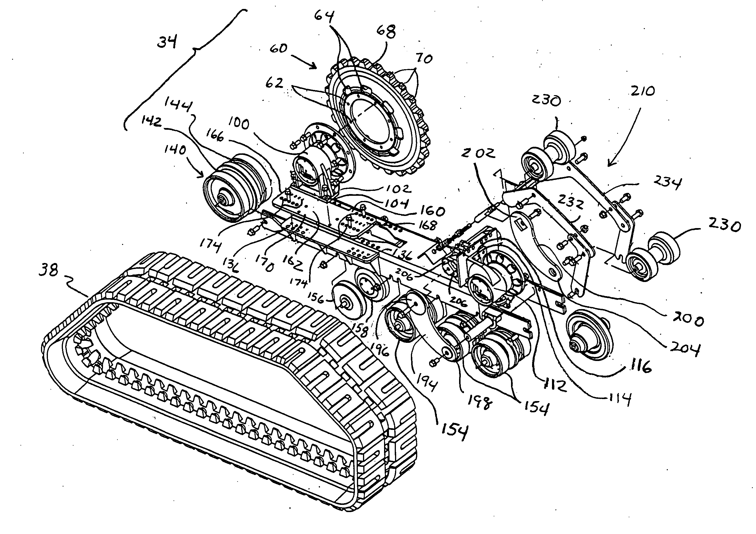
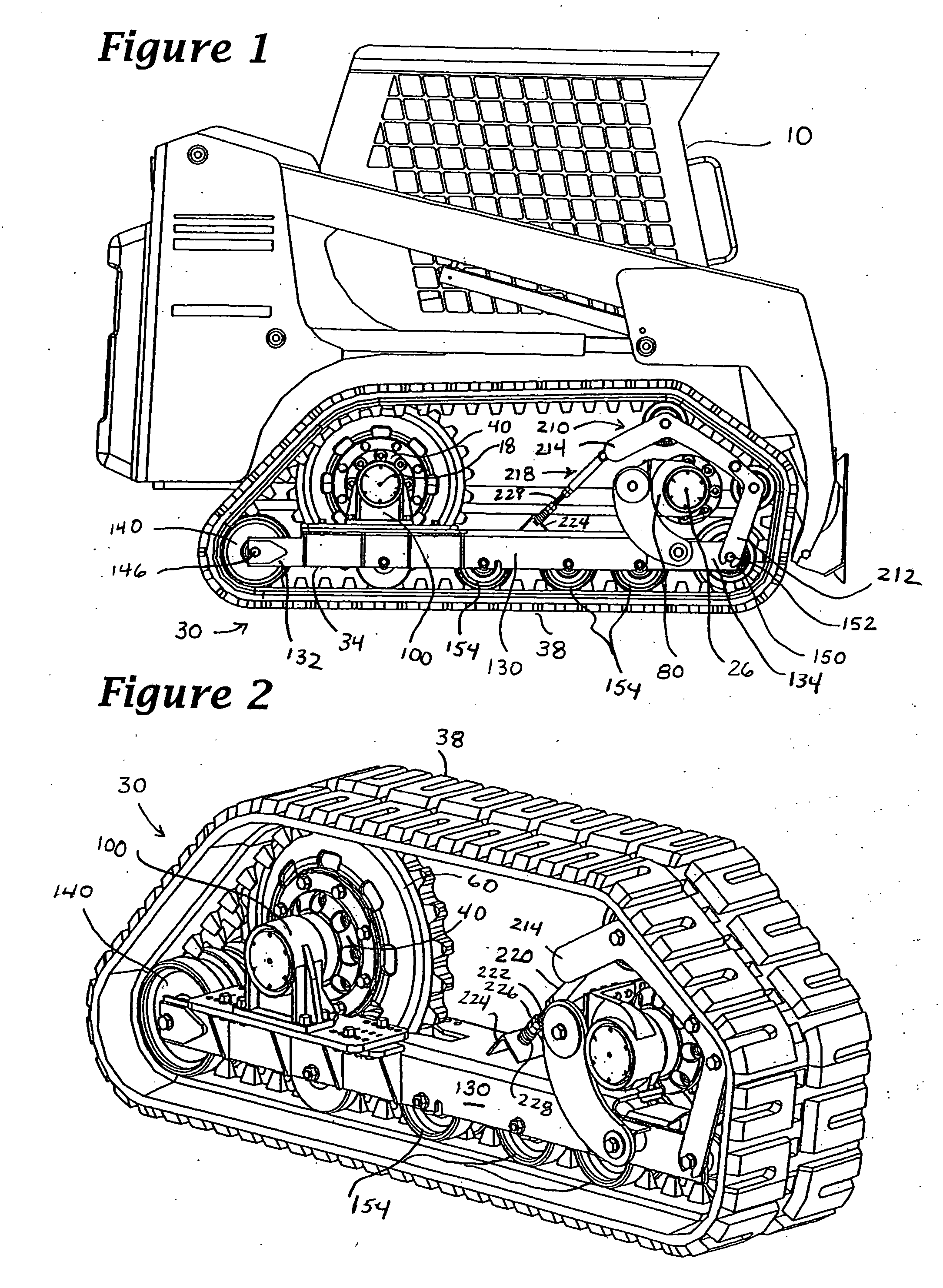
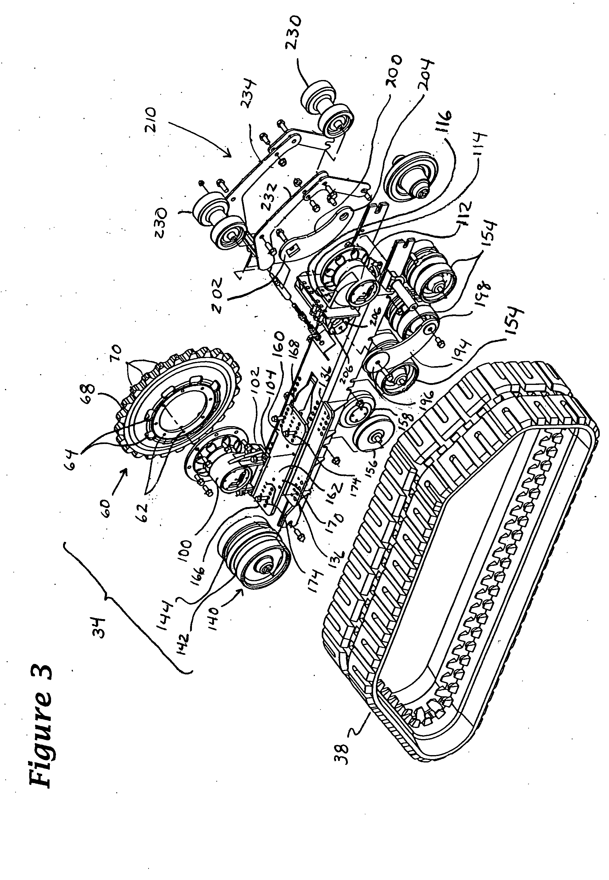
[0040] A generic skid-steer vehicle 10 having a track assembly 30 attached thereto in lieu of wheels is depicted in FIG. 1. Generally, the track assembly 30 comprises an apparatus or track carrier 34 and an endless track 38. More specifically, the apparatus 34 of the track assembly comprises a first hub assembly 40 and a second hub assembly 80 that are operatively connected to a support frame 130 by first and second attachment members 100, 112, respectively. Note that the distance between the rotational axes of the first and second hub assemblies are coincident with the rotational axes of the wheel axle axes to which they are attached.

[0041] First and second rollers 140,150 are operatively connected adjacent opposing ends 132,134 of the support frame 130 and serve to support the vehicle and to define the ground contacting extent of the endless track 38. The first and second rollers 140, 150 also redefine the wheelbase of the vehicle. Note the rotational axes 146 and 152 of the firs...


PUM


Abstract

A track assembly having first and second hub assemblies that are operatively connected to a support frame by first and second attachment members, respectively. The first and second attachment members include resilient or movable mounts that are configured so that the track assembly can be attached to vehicles whose axles or wheel flanges are misaligned or have irregular rotational movement such as runout or wobble. The attachment members may be adjustably positioned relative to the support frame to accommodate vehicles having different wheelbase lengths and axle lengths. An endless track encircles the first and second hub assemblies, and the support frame, and is drivingly engaged by one of the hub assemblies. First and second rollers, which define the longitudinal extent of the endless track, are positioned at either end of the support frame. A tensioning member, with at least one upper idler roller, positions the endless track so that it is spaced from one of the hub assemblies in a spaced relation. The track assembly increases traction and stability by providing a vehicle with an independent front suspension, a larger footprint, and a longer wheelbase. In use, each track assembly is bolted onto wheel flanges of a vehicle using existing wheel lugs and nuts.

Description

FIELD OF THE INVENTION [0001] The present invention relates generally to wheeled vehicles. More particularly, the present invention relates to a track assembly that may be used to convert construction equipment such as wheeled skid-steer loaders into tracked skid-steer loaders. BACKGROUND OF THE INVENTION [0002] Skid-steer loader machines are old and well known to the art. Originally designed to operate with only a loading scoop or a bucket, these machines have, with the provision of specifically designed attachments, evolved into multi-purpose machines capable of many diverse operations. Nowadays, a skid-steer loader machine may be configured to operate as a street sweeper, a posthole digger, a trencher, or a forklift, for example. As the number of applications of skid steer loaders increases, they may be found in use in many different environments. Often, they are used in conditions where the surface upon which they traverse is not capable of supporting the weight of the skid-stee...

Claims


Application Information

Patent Timeline
Patent Type & Authority Applications(United States)
IPC IPC(8): B62D55/084B62D55/125B62D55/14B62D55/30
CPCB62D55/084B62D55/305B62D55/14B62D55/125
Inventor LOEGERING, GEORGE A.HANSEN, RONALD S.LOEGERING, STEVEN W.
Owner ASV HLDG INC
Why Eureka
Try Eureka