Construction residue transport system

a technology for transporting systems and construction residues, applied in the direction of transportation items, packaging, large containers, etc., can solve the problems of large problems, increased concrete being used on these sites, and material becoming extremely slippery

Inactive Publication Date: 2005-07-07
MINEGAR PETER J
View PDF10 Cites 18 Cited by
  • Summary
  • Abstract
  • Description
  • Claims
  • Application Information

AI Technical Summary

Benefits of technology

[0018] The preferred embodiment of this invention consists of a construction residue transport system consisting of a container that in the preferred embodiment would be transported by means of a roll-off box transport truck and in the alternate embodiment would be a smaller unit set up on wheels as a trailer system for small jobs. In the roll-off box configuration the device will incorporate a container consisting of a tubular steel framework with a contoured sheet metal bed and a contoured polymer liner. A watertight steel door or tailgate, sealed by means of a conventional O-ring seal and toggle clamp mechanisms commonly used in this field, will open by means of a hinge located on any one of the four structural members at the back of the container. The watertight steel door or tailgate will be considerably higher than the central framework of the container to endeavor to keep material from coming out while the device is being transported and while it is being tipped up for placement on the roll-off box transport truck. Two angular braces support the upper portion of the door framework and are covered with triangular polymer panels to additionally aide in keeping material from coming out during transport and also when it is placed on the roll-off box transport truck.
[0028] Another object of this invention is to create a device with sealed angular supports for the back door or tailgate that will prevent material from going out the sides when the device is tipped during the loading process of placement on a roll-off style transport truck.
[0030] Another object of this invention is to create a container that can be easily sealed with a tarp over a strap that diverts rainfall to the sides of the device.
[0031] Another object of this invention is to create a device that will hold the residue from the cleanup of concrete pumps and concrete ready mix delivery trucks and allow the material to slide out easily after it has reached a solid state.
[0033] Another object of this invention is to create an area with non-slip steel grating where the operators of the concrete pumps and concrete ready mix delivery trucks can safely stand when cleaning their equipment.
[0035] A further object of this invention is to create a device that can be adapted at a smaller scale as an integrated trailer unit to be pulled on it's own wheels by a truck to smaller construction sites.

Problems solved by technology

With the increasing awareness of environmental controls and the confinement of construction projects, places to put this residue have become scarce and the amount of concrete being used on these sites has increased greatly.
Dumping this material where all or any part of it will get into the storm drain system has been found to be a major problem.
Construction projects in the inter-city and freeway areas present the greatest problems for the cleanup and removal of this residue.
This material becomes extremely slippery when it is on the surface of the ground.
On construction projects during the winter or when it is raining the residue from the cleaning and dumping process gets even worse when the wash-down water and the rain water accumulates in low areas on the ground and is extremely hard to handle.
The material is slippery and can harden after a period of time without construction personnel being aware of where it is located.
The structure of this device would not lend itself to the containment of the materials involved with the wash-down of concrete pumps and concrete ready mix delivery trucks which hardens and most often requires the removal in a solid state from the container.
This device will not support the weight of the residue from the cleanup of the concrete pumps or the concrete ready mix delivery trucks.
The device is designed to take the shape of conventional containers and has not been designed with any unique features or for any specific purposes.

Method used


Image

  • Construction residue transport system
  • Construction residue transport system
  • Construction residue transport system

Examples


Embodiment Construction

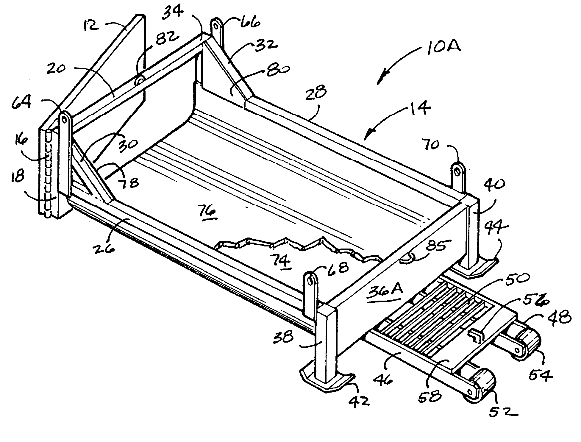
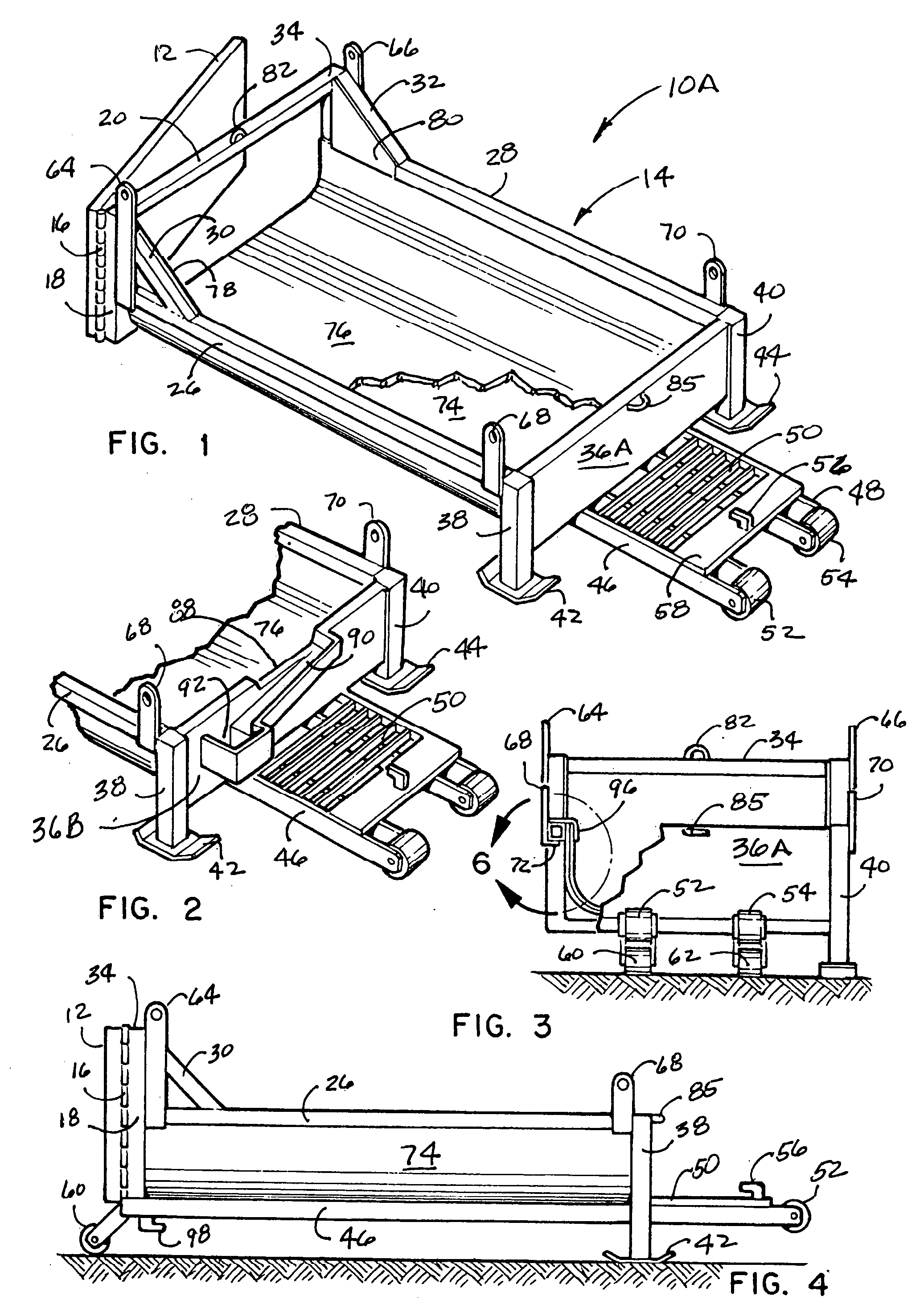
[0047] Referring now to the drawings, wherein similar parts of the invention are identified by like reference numerals, there is seen in FIG. 1 a perspective view of the preferred embodiment of the construction residue transport system 10A with the watertight door or tailgate 12 partially open at the back of the container bed 14. The watertight door or tailgate 12 is shown pivoting from the side by means of a hinge 16. It must be understood that the watertight door or tailgate 12 can pivot from any one of the rear steel side structural members 18 or 22 or the top or bottom steel structural members 20 and 24 attached at the rear of the container bed 14 and still remain within the intent of this patent. The watertight door or tailgate 12 is sealed by means of a typical conventional O-ring seal and toggle clamping mechanism or any other commonly used mechanism in this field. The container bed 14 framework, consists of the rear steel side structural members 18 and 22 along with top and ...


PUM


Abstract

A system for the containment and removal of the residue derived from the cleaning of concrete pumps, pump hoses, concrete ready mix delivery trucks and similar materials and equipment located at construction sites, to a recycle center or dumpsite. The system may consist of a roll-off style container or a mobile trailer unit with an enlarged watertight back door or tailgate. The container will incorporate a steel non-slip grating for operators to walk on and folding ramps that can be incorporated on the sides of the grating. An alternate embodiment of the front wall will have a unique weir and gutter to direct the overflow water and scum into a filtration reservoir.

Description

FIELD OF THE INVENTION [0001] This invention relates to the field of containing and removing residue from a construction site to a recycle center or dumpsite. And, more specifically, to the removal of the residue from the cleanup process of the concrete pumps and concrete ready mix delivery trucks or other similar materials or mixers at construction sites by means of a unique portable construction residue transport system. The term residue in this patent primarily refers to the composite cement, sand and gravel that remains in the pump, pump hoses, the ready mix delivery truck barrel and the shoots used to disperse the mixture. Additionally there are the hand tools and the outside surfaces of the equipment that require wash-down. On occasion, there is a small quantity of the mixture left in the equipment that is not needed and this overrun must be disposed of on-site. Other mixtures and construction equipment cleanup, such as masonry mortar mix and plaster mix, may equally fall into...

Claims


Application Information

Patent Timeline
Patent Type & Authority Applications(United States)
IPC IPC(8): B60P1/28B65D88/00
CPCB60P1/286
Inventor MINEGAR, PETER J.
Owner MINEGAR PETER J
Why Eureka
Try Eureka